Solutions in Battery Technology Testing
Hazard screening, safety testing and performance characterization
Discover how our battery testing solutions provide you with a flexible and versatile toolkit for accelerating every stage in the development of safer, more powerful batteries.
- Glossary of Key Terms
- Understanding Battery Thermal Behavior: Why should you care? Workflow
- What is a Battery?
- What Matters in Battery Technology Development
- Thermal Behavior in the Battery Development Stages
– Cell Development
– Cell Assembly
– Cell Integration - Solutions in Battery Technology Testing
- References

Glossary of Key Terms
Battery – a group of interconnected cells
Cell – an electrochemical cell, consisting of one anode, one cathode, electrolyte, and a separator
Module – group of cells interconnected in a single unit
Pack – interconnected modules, with the required auxiliary subsystems for mechanical support, thermal management, and electronic control
Cathode – positive electrode in a cell
Anode – negative electrode in a cell
Separator – provides electrical separation between the anode and cathode
Solid Electrolyte Interface (SEI) – a layer in Li-ion batteries which is formed on charging. It allows Li intercalation, but is electronically insulating and prevents electrolyte decomposition
Electrolyte – charge conducting medium in a cell or battery
Specific energy – how much energy is stored in a battery. Also known as energy density
Specific power – indicates how rapidly energy is delivered
Adiabatic Calorimetry – allows the heat generated by a sample to be retained within the system, ensuring the measured thermal energy changes are solely due to the sample self-heating
Isothermal Calorimetry – the sample temperature is maintained at a constant temperature during testing, enabling any thermal energy changes within the sample to be accurately measured
Thermal Runaway – a situation where an increase in temperature of a system causes additional thermal events to occur, increasing the temperature of the system further in an uncontrolled positive feedback
Thermal Management – means for controlling the temperature of a system to avoid localized overheating and to ensure heat dissipation is greater than heat generation
Understanding Battery Thermal Behavior: Why should you care?
Batteries are everywhere, powering everything from consumer electronics to electric vehicles (EV). As such, there is a growing demand for batteries with higher energy densities, quicker charging times, and longer lifetimes. This necessarily introduces additional safety considerations when it comes to battery development and optimizing battery behavior.
Broadly speaking, batteries are sensitive to both thermal and electrical changes. Batteries with high energy densities tend to be more thermally unstable, and using higher current to give faster charging times will usually reduce both the stability and lifetime of the battery. Small-scale fires involving batteries, exemplified by the grounding of the entire fleet of Boeing 787-Dreamliners [1], illustrate the potential hazards that batteries pose. The United States’ FAA has listed 290 aircraft incidents between January 2006 and August 2020 that involved “smoke, fire, extreme heat or explosion” in which lithium ion battery-powered devices were implicated [2]. Larger numbers of more powerful cells, such as those used in electric vehicles (EVs), represent a potentially greater hazard, if they are not properly characterized and managed.
Therefore, there is a need to understand the impact of thermal behavior on the safety, electrical performance, and lifespan of a battery. Understanding this behavior helps battery developers to define, understand and enhance the boundaries of safe and optimum operation.
The boundaries of operation are represented schematically in Figure 1. The inner square is the Optimum Zone. This area represents the normal thermal and electrical operating bounds of the battery. The Safe Zone of operation expands beyond the optimum area. Within the Safe Zone, the battery performance and lifespan are degraded because of the operating conditions used, but it does not yet pose a safety hazard. Beyond this area, the battery will cease to function correctly and will represent a significant safety hazard: the Dangerous Zone.
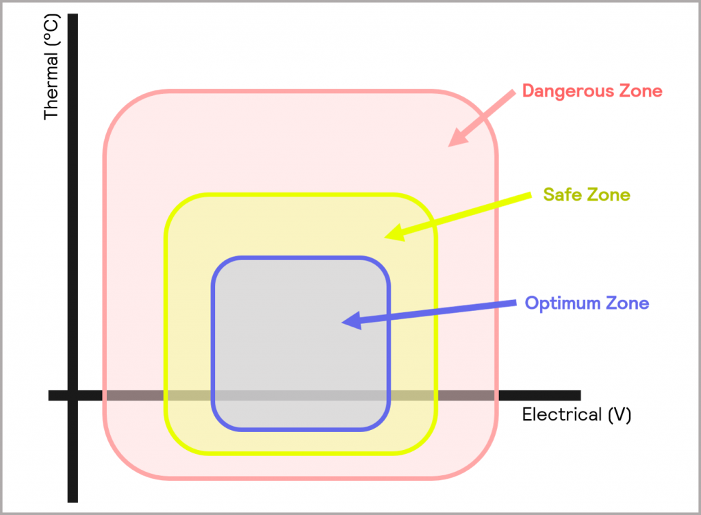
Figure 1: the Optimum, Safe and Dangerous Zones of operation
Considerations of the boundaries of operation represent a central theme throughout battery development, although the emphasis is likely to be on different aspects at different stages of the workflow. For example, within Cell Development the emphasis may be more on enhancing the Optimum and Safe Zone of operation, whereas in Cell Integration the focus shifts more to defining and controlling the boundaries of the Dangerous Zone to ensure safe use.
Figure 2 depicts the battery development workflow from component to cell, to module, to pack, loosely grouped in terms of Cell Development, Cell Assembly, and Cell Integration. Throughout the workflow, some key questions and challenges must be addressed.
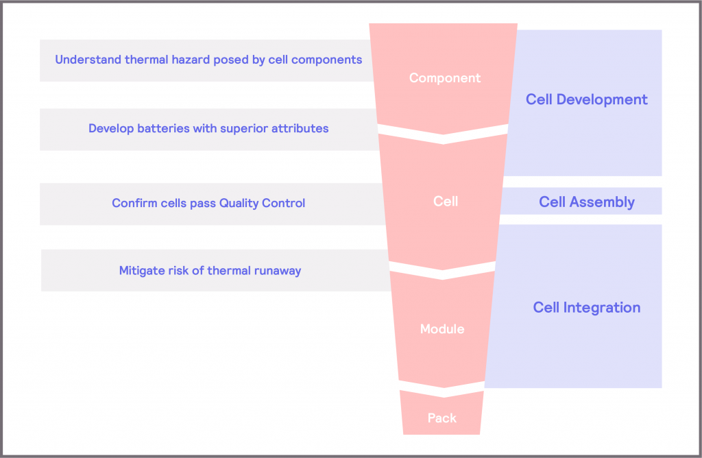
Figure 2: key questions and challenges in the battery development workflow
- Cell Development focuses on developing cells which lead to batteries with superior attributes. During cell development, the thermal hazard of the components is evaluated, so that these materials can be optimized to minimize the risk posed and to inform strategies to mitigate the risk. More broadly, it considers the performance, lifespan, and safety of the cell as a single entity so that these attributes can be developed and optimized.
- Cell Assembly requires a Quality Control step, where the intention is to demonstrate that the cell meets the intended performance criteria. This allows the cell manufacturers to demonstrate a stated performance and allows cell integrators to confirm that the cells they purchase meet their requirements.
- Cell Integration focuses on defining the means of mitigating the risk of thermal runaway when the cell is integrated within a module or pack. This can range from determining the thermal management requirements of the cell and module when operated under normal operating conditions, through to defining the safe operating limits of the system to ensure the battery is not subjected to stress conditions. There is also a considerable amount of research into furthering understanding of the mechanisms of thermal runaway and thermal propagation at this stage [3] [4] [5], which can then inform new Cell Development strategies.
In this article, we will explore each stage of the workflow and the considerations within it in more detail, but before that, we will take a step back and review exactly what a battery is and the considerations involved in developing them.
What is a Battery?
A battery is a form of energy storage. It allows for the conversion of chemical potential energy into electrical energy, which can be used to power a range of devices. As Figure 3 illustrates, it typically consists of at least one positive electrode (the cathode) and a negative electrode (the anode), electrically separated by a membrane (the separator). These components are soaked in an electrolyte, which acts as a charge conducting medium. The chemical reactions that take place between the electrolyte and the electrodes result in the production of ions and the build-up of electrons at the anode. The ions pass through the electrolyte to the opposite electrode from which they were generated, whilst the electrons at the anode pass through an external circuit to the positive cathode, so that charge is balanced. The flow of electrons provides the electrical power for the device that is connected to the battery.
What Matters in Battery Technology Development?
There are six main considerations when developing new battery technologies: specific energy (energy density), specific power, cost, life span, performance, and safety [7]. Inevitably, there are trade-offs between these criteria: optimizing for one element compromises another. The relative performance of a battery material in each of these areas is often depicted graphically on a spider diagram or a radar plot, as illustrated in Figure 5. Frequently, the application of the battery will dictate which properties are prioritized.
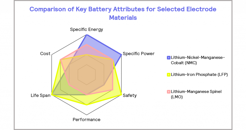
Figure 5: the relative performance of selected electrode materials in key battery attributes, where the further the plot extends radially, the better the performance in the given attribute
Specific Energy and Specific Power
Specific energy can be thought of as “how much energy can be stored within the battery”. Specific power indicates how rapidly the energy is delivered. These terms are illustrated conceptually in Figure 6.
Therefore, devices like power tools typically have a high specific power but a reduced specific energy, whereas a typical AA battery will have a high specific energy but relatively low specific power. This is because a power tool requires a delivery of high energy for a relatively short period of time, whereas a longer lifetime is more desirable for a typical AA battery. For EV batteries, specific power equals or exceeds that of internal combustion engines, so research efforts are focused on increasing specific energy for a given power level [7]. Usually, this means concentrating on developing high capacity cathode and anode materials. However, these higher capacity materials tend to have lower thermal stability, so there is a trade-off between the attributes depending on the end application.
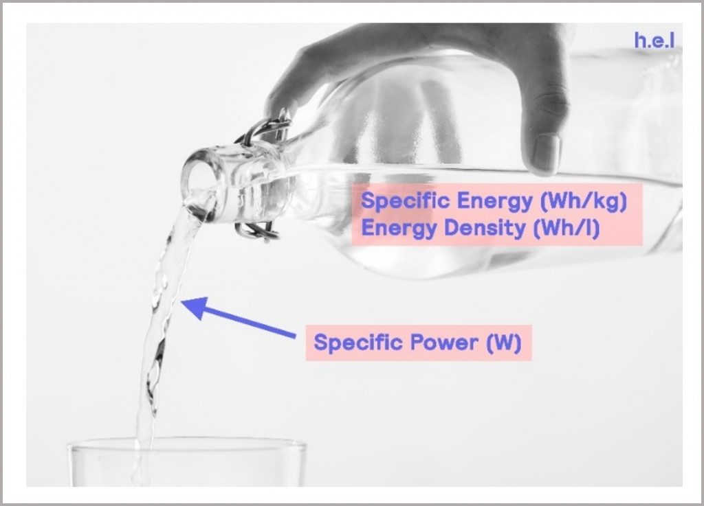
Figure 6: visual representation of specific energy and specific power
Safety
Thermal stability, or more specifically, safety, is one of the most important criteria in battery development. This is especially true in the development of EV batteries, where the consequences of a failure would be catastrophic. The biggest concern relates to the development of a thermal runaway situation, whereby chemical reactions triggered in the cell accelerate heat release, potentially resulting in fire or an explosion.
Batteries inherently contain highly reactive and potentially hazardous chemicals, in order to deliver their stored energy. During normal use, battery cells will typically experience some level of self-heating. When batteries are combined to form modules and packs in an enclosed space, heat dissipation is reduced. Without putting additional measures in place, the battery can find itself operating under pseudo-adiabatic conditions. When coupled with the fact that the battery can be used under a range of environmental conditions and subjected to additional stresses which may exacerbate and accelerate self-heating, it is clear that understanding the thermal behavior of the battery, and managing it, is critical to safety. Some of these causes of cell failure are summarized in Figure 7 and discussed in more detail in Defining Safe Operating Limits.
There are three main types of stresses that the cell can be subjected to: mechanical, electrical, and thermal. Each of these can either lead to an increase in self-heating directly or could cause an internal short circuit, which then results in increased self-heating. If the heat generated is greater than the capacity of the device to dissipate heat, this can result in a thermal runaway and potentially lead to a battery fire or explosion. Similarly, this could happen from self-heating under normal operation, particularly as the cell ages, and its internal impedance increases. This could potentially lead to a thermal runaway if temperature management strategies are not adequate.
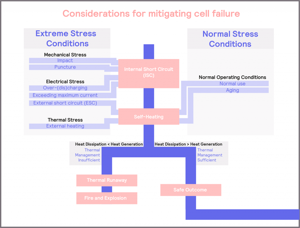
Figure 7: schematic illustrating the causes of battery failure
Performance and Lifespan
Battery lifespan considers both overall age and cycle stability. Overall age relates to the number of years a battery is expected to remain useful. Cycle stability considers the number of times a battery can be fully charged and discharged before reducing to 80% of its original capacity at full charge [7]. This aging process is known to accelerate under higher ambient temperatures, as it speeds up the degradation of the internal components of the battery.
Battery performance considers the electrical behavior under different operating conditions. Batteries can be optimized for use at low or high temperatures, but it can be challenging to engineer them for operation over a wide range of temperatures. However, it is desirable for them to be able to operate in this way, as it widens their potential number of applications.
Performance assessments include the charging rate. Batteries that charge more rapidly tend to be more desirable across a range of applications from mobile phone use through to EVs. However, rapid charging can lead to an increase in temperature of the cell if not managed with an effective temperature control system, and the subsequent thermal safety concerns which come with an increase in cell temperature.
With the sole exception of cost, thermal behavior is a unifying theme and critical consideration in all of these attributes. Therefore, understanding thermal behavior and its impact on battery behavior and characteristics is critical throughout battery development.
Thermal Behavior in the Battery Development Stages
As a critical aspect of battery development, it is valuable to consider how to monitor the thermal behavior of the battery and the impact it has on broader battery behaviors, such as safety, lifespan and performance.
In Understanding Battery Thermal Behavior, the concept of defining the Optimum and Safe Zones of battery operation as a function of temperature and voltage was introduced (see Figure 1, reproduced in Figure 8). This is also a valuable way of defining the methods and techniques for investigating and evaluating the thermal behavior of a battery.
An isothermal calorimeter maintains the cell or battery at a constant temperature, and in doing so, measures the thermal energy changes in the sample throughout an experiment or test. It is also possible to monitor the electrical output of the battery at the same time, thus delivering both thermal and electrical behavior information simultaneously. Integrating the isothermal calorimeter with a charge-discharge unit enables the automation of repeated cycling of battery cells under a variety of charge and discharge rates. Therefore, the battery can be subjected to various charge and discharge rates, or applied voltages, while evaluating the resultant thermal behavior and electrical output of the battery. Similarly, the thermal and electrical behavior of the battery can be easily assessed under different temperatures. This range of testing essentially enables the performance of the battery within the Optimum Zone and Safe Zone to be explored using an instrument, like iso-BTC, as illustrated in Figure 8.
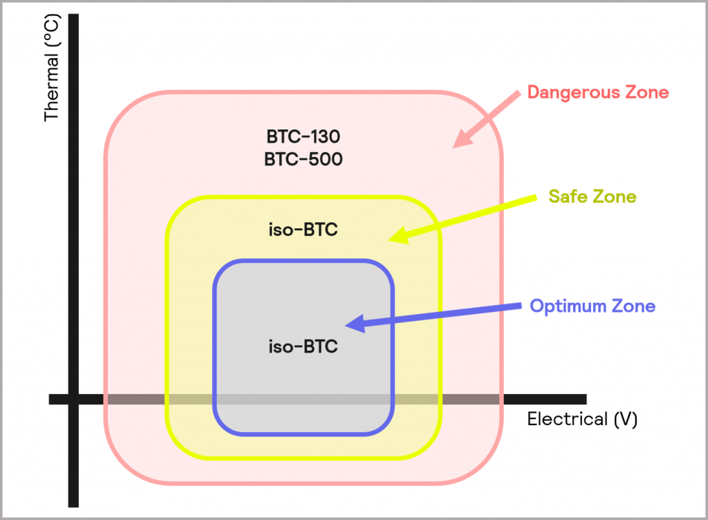
Figure 8: operating zones of the iso-BTC (Optimum Zone and Safe Zone), BTC-130 and BTC-500 (Dangerous Zone)
In contrast, adiabatic calorimeters, keep the cell or battery under adiabatic conditions, where heat generated is retained within the system. This allows the battery’s thermal behavior to be assessed under worst-case scenarios. Thermally, the temperature of the battery can be increased in a controlled manner within a safe environment to push the battery to its thermal limits. Again, such devices can also be fully integrated with a charge-discharge unit. However, in this case, the battery can be driven to voltages and discharge currents outside of the Safe Zone to probe the behavior of the battery under extreme conditions. Some adiabatic test systems also support the use of mechanical stress tests, which also result in a sudden increase in thermal energy (these will be discussed in more detail in Mechanical stress). Adiabatic calorimetry enables the battery response within the Dangerous Zone to be explored, as illustrated in Figure 8. Smaller battery cells and cell components are suited to a device like the BTC-130, and the BTC-500 is more appropriate for larger cells, small modules, and packs.
As summarized in Figure 2, and expanded in Figure 9, different questions and challenges are posed at various points in the battery development workflow and, the nature of that question or challenge will dictate which type of technique is required. In Figure 9, we consider how the questions and challenges posed can be addressed.
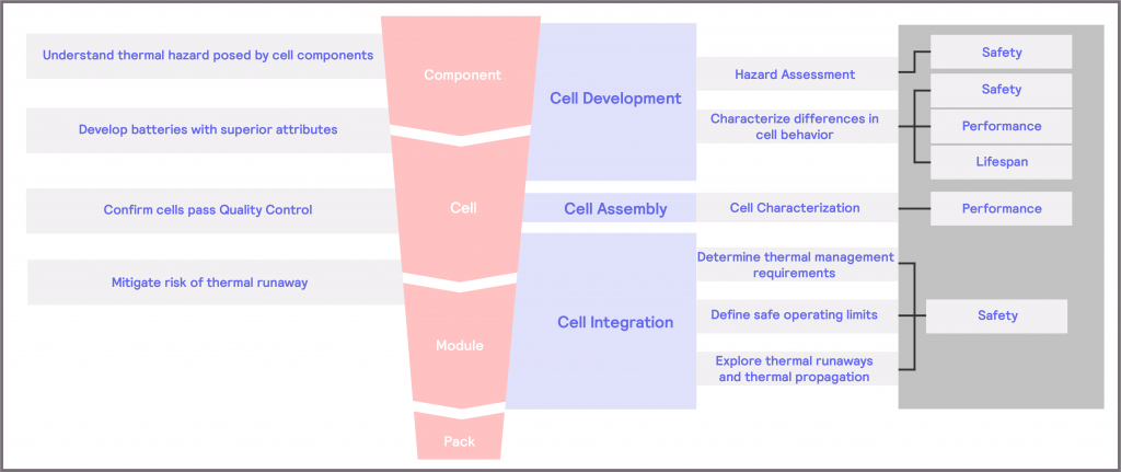
Figure 9: addressing the key questions and challenges posed within battery development.
- Within Cell Development, there is a need to understand the extent of the thermal hazard posed by each cell component. To address this, it could be valuable to conduct a hazard assessment of the materials. This very much falls within the safety attribute described in What Matters in Battery Technology Development?, and will require testing within the Dangerous Zone. Building on this, there is a need to develop cells with superior attributes. In this case, it is invaluable to characterize the differences in cell behavior. It will naturally cover safety, performance, and lifespan attributes, and will require testing of all three Zones.
- Within Cell Assembly, there is a need to confirm that cells pass Quality Control. For this, characterizing the cell is critical, which falls within the performance attribute and will require testing in the Optimum Zone.
- Within Cell Integration, the driving need is to mitigate the risk of thermal runaway. For this, there is a need to determine the thermal management requirements when the battery is operated under normal use and to identify what its safe operating limits are, to prevent exposure to extreme conditions that could cause a thermal runaway. This falls within the Safety attribute, although it will require testing within both the Safe Zone and the Dangerous Zone, as expanded on in more detail later. A third element focuses on using the same techniques to explore the mechanisms behind thermal runaways and thermal propagation. The understanding from this can then inform strategies for thermal management and can also provide insight for future Cell Development strategies.
Cell Development
The key goal of Cell Development is to develop batteries with superior attributes. Increasing the battery specific energy is a key industry focus. This tends to come with greater thermal instability. Therefore, there is also a more specific need to assess the extent of the thermal hazard posed by the individual cell components. Outside of this, there is a desire for better electrical performance over a broader range of temperatures – in other words, a desire to increase the size of the Optimum and Safe Zone of operation of the battery, as illustrated schematically in Figure 10.
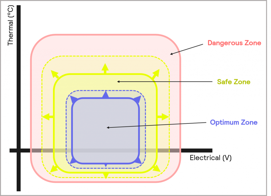
Figure 10: within Cell Development, there is a desire to widen the Optimum and Safe Zones of operation
Therefore, in terms of thermal behavior considerations, there are two main evaluations to address: hazard assessment of newly developed cell components and characterization of differences in cell behavior, both of which will now be discussed in more detail.
Hazard Assessment
There is a substantial commercial drive to develop batteries with higher specific energy. Usually, this development takes the form of focusing efforts on high capacity cathode and anode materials. However, higher capacity electrode materials tend to be more thermally unstable. In addition, other components within the cell can be highly flammable. It is well recognized that the decomposition of one component can then trigger further reactions and decompositions of other components, leading to rising temperatures within the cell and potential thermal runaway scenarios (discussed in more detail in Thermal Stress).
Therefore, it is clear that the thermal stability of the components within a cell will have a significant impact on its overall safety, and as a result, it must be assessed and understood.
Electrode Materials
Higher capacity electrode materials, like those desired for high specific energy batteries, typically have lower thermal stability and less desirable behavior when a thermal event occurs. Therefore, it is imperative that the thermal stability of these compounds is characterized and understood, both in terms of optimizing and developing new electrode materials [8], and so that the required system-level safety measures are in place [7].
For example, the likes of lithium nickel manganese cobalt oxide (NMC), which is often used in EVs, and lithium manganese oxide (LMO), are cathode chemistries known to be prone to thermal runaways [8]. In contrast, lithium iron phosphate (LFP) is much more thermally stable but has a lower energy density. Therefore, if a higher energy density but more thermally unstable material like NMC is required for the application, it is necessary to ensure that a very efficient cooling system is in place to prevent the early stages of thermal runaway, along with precise state-of-charge (SOC) monitoring and cell-discharge balancing [7]. Characterizing the material’s thermal properties from the outset allows this to be factored in further into development.
Electrolytes
Electrolytes are often highly flammable, as they are normally based on aprotic organic solvents, like lithium hexafluorophosphate in propylene carbonate. This poses a significant hazard because if self-heating from the battery triggers the decomposition of the electrolyte, it is likely to result in the formation of gases, which in turn will lead to the generation of substantial overpressure within the cell, followed by venting and/or rupture. If fluorinated compounds are used in the electrolyte, this will result in the formation of hydrogen fluoride, which is toxic and corrosive. Flame retardant additives can be added to reduce this flammability, and alternative electrolytes with better thermal stability (higher onset temperature of decomposition) are the subject of research [9]. Similarly, in recent studies, room temperature ionic liquids that have low volatility are showing promise as lower hazard electrolytes [8]. Therefore, the onset temperature of decomposition of the electrolyte is a vital piece of information to determine, as is an understanding of the composition and toxicity of the decomposition products formed.
Separator
The separator, which prevents electrical contact between the electrodes, is typically made of polyethylene (PE), polypropylene (PP), or laminates of both. It is a thin, microporous membrane which allows lithium ions to pass through, but prevents electrical contact between the electrodes. Clearly, if the separator breaks down, there is a risk of an internal short circuit. Therefore, it is important to be able to identify the temperature point at which this decomposition will happen. However, as the polymer melts, the pores in the layer become blocked, which can afford a certain degree of protection from a short circuit or overcharge. Therefore, it is also valuable to determine the extent to which the separator shutdown helps to dampen the risk of thermal runaway – highlighting why it is also important to perform safety tests on the cell as a single entity further into development [10].
An adiabatic calorimeter, such as the BTC-130, facilitates the use of small volume test vessels for the assessment of cell components, in addition to supporting the testing of small battery cells. This enables the thermal stability testing of individual cell components under adiabatic conditions and it allows the onset temperature of decomposition of each component to be determined under worst-case scenarios [4]. This information can then be used to optimize the development of the component and provide insight into the required cell design and thermal management strategy.
Characterizing Differences in Cell Behavior
It is recognized that optimizing for anyone of the performance-related attributes depicted in Figure 5 (higher specific energy, higher specific power, a longer lifespan, better electrical performance, and improved safety of the device) will necessarily lead to a compromise in performance of another.
Therefore, being able to characterize and understand performance across these metrics enables optimization of the required trade-offs to be done.
Safety
In addition to the safety considerations of the cell components, it is also valuable to probe the safety performance of the cell as a single entity.
Adiabatic calorimeters, such as the BTC-130 and the BTC-500, enable stress tests to be carried out on the cells, probing their response to more extreme operating conditions. For example, the tests can be combined with in-operando techniques to further understanding of the structural changes and degradation effects which occur under abuse conditions [11] [12]. It can also yield information about cell safety performance and inform decisions about cell design.
Like the iso-BTC, they are also able to support the full integration of a charge-discharge unit. As they are able to maintain “worst-case,” adiabatic conditions for testing, the BTC-130 and the BTC-500 can be used to determine the absolute limit of safe, repeated use of a battery cell, until the heat generated by continuous use causes the onset of self-heating [13].
Understanding a cell’s safety performance can also inform cell design, such as what safety devices are required in a cell (e.g., over-pressure relief valves). Therefore, the cell design is also critical in terms of mitigating and controlling safety hazards.
There are three main types of cell: prismatic, cylindrical and pouch cells [14].
- Prismatic cells are mechanically robust. They have a high packing density, but a lower energy density and are more expensive. They typically have a safety vent in order to release gases generated in the case of a build-up of pressure during a thermal runaway. If the vent is too small to release the pressure that may be generated in a thermal runaway for a particular cell configuration, the cell can rupture or even explode.
- Cylindrical cells also have good mechanical stability, have a high energy density, and are cheaper to manufacture. However, they have poor packing efficiency and, although they do not swell in operation, if there is a build-up of pressure, the jelly roll (the rolled-up layers of anode, separator, and cathode) can be expelled from the casing.
- Pouch cells have a higher energy density and are much lighter than both cylindrical and prismatic cells. They are also relatively cheap to manufacture, but their structural robustness is poor: they require an additional mechanical support to protect them during operation. They can swell during operation, but they do not have a safety valve or venting mechanism. However, the sealing points on the cell have a low resistance to high pressure, so in the event of a thermal runaway with a build-up of pressure, these sealing points often function as a de facto pressure valve. The pouch cell design may also be more effective at preventing a thermal runaway, as its less constrained design means that the electrodes are not forced to maintain close contact. They also exhibit smaller internal temperature gradients when compared to prismatic cells. However, the mechanical construct required for greater physical robustness can lead to additional weight in the overall system design.
The type of cell design chosen will be dependent on the end application it will be used in, alongside any safety considerations with regards to the thermal stability of the cell components, and the overall thermal stability properties of the cell.
Performance
It is recognized that batteries are temperature- and voltage-sensitive products [8]. This means that the battery’s thermal behavior and electrical performance will be sensitive to the conditions under which it is operated. Improving performance across a wide range of conditions is often a key focus in the development of new cells. The aim is to develop cells which can operate at an optimum level under a broader range of charge and discharge conditions and temperatures [7].
During cell development, researchers may experiment with different battery chemistries and different electrode compositions, and various types of battery cell, as all will influence battery performance. It then becomes critical to characterize the thermal behavior and electrical performance of the cells under different operating conditions in order to optimize their development.
An isothermal calorimeter, such as the iso-BTC, enables the impact of these factors to be investigated. Isothermal calorimetry maintains the cell or battery at a constant temperature and can measure the thermal energy changes in the sample over the course of an experiment or test. Integration of a charge-discharge unit with an isothermal calorimeter enables the automation of repeated cycling of battery cells under a variety of charge and discharge rates. This means that it is capable of simultaneously recording both the battery’s electrical performance and the heat evolved under different operating and environmental conditions.
The data generated on how battery efficiency, charging and discharging capacity, and heat evolved vary with temperature and charge or discharge rate can be used to model battery performance and enhance understanding of battery behavior for cell development.
In Case Study 1, we examine how the iso-BTC can be used to explore battery electrical performance over a range of temperatures.
Lifespan
Lifespan covers both cycle stability and overall age of a cell or battery. Cycle stability is defined as the number of times a battery can be fully charged and discharged before dropping to 80% of its original capacity at full charge. In contrast, overall age is the number of years a battery is expected to remain useful [7].
Cells degrade over time and when undergoing repeated charge-discharge cycles. Cycling can cause structural changes in the electrode material, which impacts its capacity to intercalate lithium ions. The impedance of the battery generally increases as the battery ages, due to these structural changes. This also causes the degree of self-heating to increase with age.
Therefore, it is important to understand the impact of aging in order to optimize lifespan performance during cell development.
Isothermal calorimeters are able to facilitate these studies, as they can support the automated, repeated cycling of cells to mimic the aging process, whilst monitoring the thermal behavior and electrical performance of the battery. Case Study 2 demonstrates how the iso-BTC can be used to investigate the effect of accelerated aging on battery behavior.
CASE STUDY 1:
Battery Efficiency and Capacity at Different Temperatures
In this study, the temperature dependence of a triple gel cell battery, with a stated capacity of 2.2 Ah undergoing charge/discharging cycling, was investigated. The cell was charged at 5 A and discharged at 8 A, at temperatures between 60 °C and 0 °C, as illustrated in Figure 11. The pink trace represents the battery temperature and the controlling heater power is the blue trace. The heater power helps to maintain the battery under isothermal conditions, compensating for any thermal changes in the battery as a result of the charging/discharging cycling. The peaks and troughs relating to the charge and discharge steps are labeled on the blue trace: peaks relate to endothermic activity, whereas troughs are exothermic. It is clear that as the temperature of the battery drops, there is a change in the heater power profiles: the charging step becomes exothermic at lower battery temperatures.
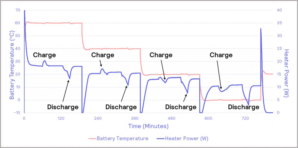
Figure 11: charge/discharge cycles of triple gel cell battery
Digging deeper, the heat flow power profile, which is the rate of thermal energy evolved from the cell, can be extracted for the charging and discharging events. These are illustrated in Figure 12. As well as the previously identified transition from endothermic to exothermic behavior, there is also evidence of a small exothermic peak in the heat output in the charging data (occurring after about 80 min), which grows in magnitude as the temperature is reduced, as can be seen in Figure 12a. A similar pre-peak is also observed in the discharging data in Figure 12b. It is possible that this is due to a solid-state transformation within the battery, a hypothesis that could be confirmed with orthogonal microstructural analysis techniques.
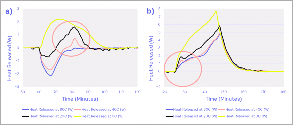
Figure 12: heat flow power profiles; (a) – charging, (b) – discharging
The battery’s capacity also has a strong temperature dependence. The chart in Figure 13a shows the charge and discharge profiles for the battery, with the charging current in blue and the discharging current in black. The heat release is plotted in pink. Integrating the charging and discharging profiles enables the charge and discharge capacity of the battery to be determined. This can be calculated at each temperature the battery is subjected to, resulting in the chart in Figure 13b. At higher temperatures, the battery has a higher capacity of charge. Taking the charge/ discharge ratio gives the efficiency of the battery, as depicted in Figure 14. This shows that the efficiency of the battery increases with increasing temperature under the conditions tested.
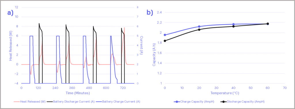
Figure 13: a) – charging/discharging cycles against battery heat release; b) – charge and discharge capacity of the battery
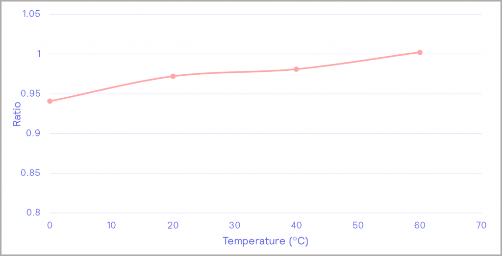
Figure 14: battery efficiency as a function of temperature
Thus, the efficiency of the battery and its heat flow properties during charging and discharging have been defined over a range of temperatures. This characterization can be used to compare different cell performance for different electrode compositions, cell chemistries, cell types, SOC of the battery, and cell history. For more information on the investigation, a copy of the case study can be downloaded here.
CASE STUDY 2:
Investigating the Effect of Accelerated Aging on Battery Behavior
In this study, the impact of cell aging on cell thermal behavior and electrical performance was investigated. The iso-BTC supports the cycling of batteries under normal charge/discharge rates (i.e. within the Optimum Zone) and under abnormal charge/discharge rates (i.e. within the Safe Zone, but no longer optimum). In this study, a pouch cell with a C-rate of 16 A was operated under both normal and abnormal conditions. The C-rate is the safe limit that a cell can be operated at (i.e., the normal rated capacity that a cell can charge or discharge within an hour), as defined by the manufacturer.
The cell was cycled between 2.8 V and 4.15 V at a 1 C charging rate and 1 C discharging rate, before being extended to a 0.5 C charging rate and 5 C discharging rate. Therefore, the extended test took the charging current from 8 A to a discharging current of 80 A and represented abnormal testing conditions to probe the extent of the Safe Zone of operation.
When operated with a 1 C charging and discharging rates, the charging and discharging thermal energy remained relatively constant, as depicted in the Figure 15a (heat release is derived from heater power; for more information, see our on-demand webinar). The number of automated cycles could be repeated for an extended period of time in order to elicit a greater understanding of the potential lifespan of the battery but was not undertaken in this particular study.
When subjected to abnormal C-rates, the thermal energy released increases per cycle, as illustrated in Figure 15b. In principle, this increase in temperature could lead to a thermal runaway if not adequately managed within the battery management system (BMS).
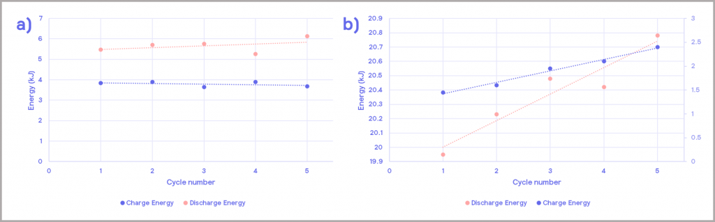
Figure 15: thermal energy release during charging and discharging cycles; a) under normal operating conditions; b) under abnormal operating conditions
Cell Assembly
Within Cell Assembly, the aim of testing is to confirm that the cells manufactured pass Quality Control (QC). This is important for both cell manufacturers to demonstrate a stated performance, and also for battery integrators further downstream who wish to check the performance of the cells they have purchased. This is achieved by defining the performance characteristics of the cell and testing against these specifications.
Cell Characterization
The cell can be characterized on pre-defined attributes, such as battery efficiency and heat evolved at specified temperatures and C-rates.
The data from isothermal calorimeters (such as the iso-BTC) can provide information on thermal behavior, cell capacity, and cell efficiency over a range of defined temperatures and discharge rates. The values can then be used to define the specifications of the cell, from which QC testing can be based. Some QC labs may wish to also subject batteries to stress tests as part of their production checks.
Cell characterization can also be used by cell integrators to compare the performance of batteries from different suppliers, to help identify which would be best suited to their end application [15].
Cell Integration
Within Cell Integration, the focus switches almost exclusively to safety considerations in terms of the key battery attributes identified in What Matters in Battery Technology Development?, and addressing the challenge of mitigating the risk of thermal runaway.
Cells generate heat on use, and they generally produce more heat as they age. When they are packed closely together within a module or pack, heat dissipation will be reduced. This can lead to a scenario where the heat generated exceeds the heat dissipated, leading to a potential thermal runaway situation, unless additional measures are implemented. In addition, the battery can also be subject to additional stresses and operated under a range of conditions, which may accelerate the rate of self-heating. These various potential causes of thermal runaway are summarized in Figure 16, which is a more detailed version of that presented in Figure 7, and will be referred to throughout this section.
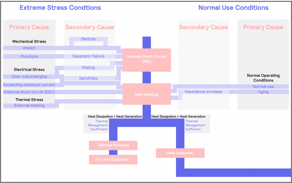
Figure 16: Detailed schematic illustrating the causes of battery failure
Therefore, there are two distinct elements to cell integration:
- Managing the heat generated as part of the normal use of the battery
- Implementing mitigation strategies to avoid the cell being subjected to extreme stress conditions
This translates into two areas of evaluation:
- Determining thermal management requirements for the battery
- Defining the safe operating limits of the battery
Although both relate to battery safety, they require two different techniques:
- Thermal management involves probing the battery response in the Optimum Zone. Therefore, an isothermal calorimeter is the instrument of choice for this analysis
- Defining the safe operating limits involves pushing the battery beyond its safe boundaries, identifying where those boundaries are, and understanding the extent of the hazard if they are exceeded. In this case, an adiabatic calorimeter should be chosen as the battery is being tested in the Dangerous Zone
This is illustrated schematically in Figure 17.
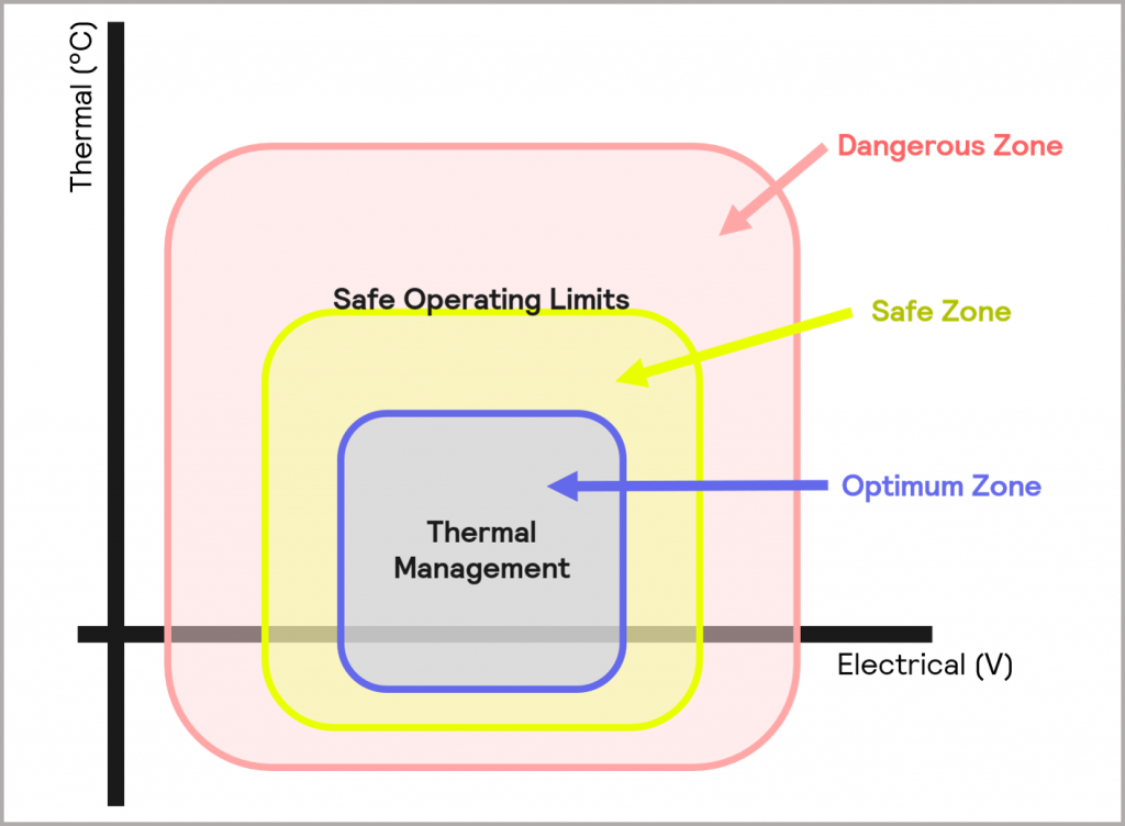
Figure 17: Safe Operating Limits can be determined from probing battery performance in the Dangerous Zone, whilst data for Thermal Management requirements can be derived from probing the Optimum Zone of operation
The third element related to addressing the challenge of mitigating the risk of thermal runaway focuses on developing a deeper understanding of the mechanism of thermal runaway and thermal propagation. This knowledge can then be used to inform management of thermal behavior and also provide insight for future cell development.
Determining Thermal Management Requirements
Cells will generally produce heat on discharge and, as they age, the heat generated will slowly increase due to the increase in internal impedance of batteries on repeated cycling. In other words, a cell’s electrical performance will decline over use. Furthermore, the cells within a module may not exhibit uniform properties upon cycling [14]. This can cause a potential imbalance within the module, which could trigger a safety hazard and/or affect battery electrical performance and life span.
Without careful management, this self-heating can result in localized overheating and trigger a thermal runaway. It is also important that the battery is carefully managed to minimize the degradation over time and the impact this has on performance [16]. Operating the battery at high temperatures will lead to side reactions and increase the internal rates of thermal reactions. This can lead to even greater heat generation, higher temperatures, and possibly a thermal runaway condition. These scenarios are illustrated in Figure 16.
Therefore, it is important to be able to determine thermal behavior over different operating and environmental conditions, so that the appropriate thermal management requirements can be implemented.
Typically, battery systems use convective thermal management to avoid the development of a rapid increase in cell temperature. The physical arrangement of cells within a module or pack are essential in governing heat transfer, as is optimizing the heat capacity and heat transfer rate of the coolant or heat sink used. The coolant is usually either air, liquid, or a phase-change material (PCM). The thermal management system could range from the inexpensive use of a small fan to circulate air through the battery chamber, to a more expensive option involving the utilization of a temperature-controlled liquid cooling circuit which passes across the cells in a pack [16]. Whereas the former might not allow the battery to be used at high charging or discharging rates under all conditions, the latter could allow the temperature to be regulated evenly across the cells in the pack, allowing for the battery to be utilized under a wider range of operating conditions and temperatures. A PCM can form part of a structure that is integrated into the pack, so it is in direct thermal contact with the cells, as illustrated in Figure 18. It adds additional mass (and cost) to the system, but this extra thermal mass helps to absorb the heat given off by cells, slowing their temperature rise. Depending on the design, it can sometimes melt if the temperature continues to rise, limiting the peak temperature. The structure also provides a fast heat transfer through the battery module, minimizing the temperature difference between cells in a module [16].
The choice of thermal management strategy will be dependent on the thermal behavior and electrical performance of the cells and module being used, and the device’s end application. Isothermal calorimetry enables cells, modules, and packs to be characterized over a range of temperatures and operating conditions. The data generated can then be used to help select the most appropriate form of thermal management.
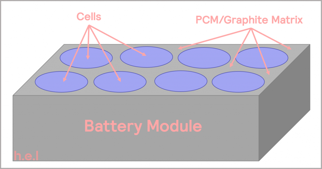
Figure 18: schematic illustrating a battery module with PCM/graphite thermal management, adapted from [16].
Defining Safe Operating Limits
Until now, we have only considered managing the thermal challenges posed by normal operation of the battery. It is also vital to understand how the battery will respond to other stress conditions which it could be subjected to during operation, so that these scenarios can be mitigated and avoided. Subjecting batteries to abuse, or stress tests is the focus of a range of battery safety testing regulations [6] [17]. There is a lot of commonality between these regulations, and they cover the same kind of stress tests; for more information on these regulations, please see reference [14].
There are three main sources of stress that the battery or cell can be subjected to: thermal, electrical, and mechanical. A more detailed figure illustrating these potential causes of cell failure is given in Figure 16. As can be seen, with the exception of a scenario where the puncture test causes the cell to be forced open, all other causes of cell failure will result in increased self-heating, which can lead to thermal runaway, and then ultimately, to a cell fire or explosion. This underlines the importance of understanding cell thermal behavior under different stress conditions.
Thermal Stress
Thermal stress tests provide the data to help define the safe working temperature of the battery [18]. The biggest safety concern relates to the development of a thermal runaway situation, whereby chemical reactions triggered in the cell exacerbate heat release, potentially resulting in fire or explosion. As noted previously, the cells self-heat under normal operation and within a battery are packed closely together. Therefore, an increase in temperature from external sources is likely to accelerate self-heating, potentially leading to a thermal runaway if mitigation strategies are not in place.
Overheating
Taking the specific example of Li-ion type batteries, an increase in temperature will cause the rate of electrochemical reaction to increase, but it is also accompanied by a more rapid accumulation of waste products from side reactions within the battery chemistry. These side reactions will result in a faster reduction of capacity. Furthermore, as the temperature continues to increase (around 85-120 °C), the SEI (solid electrolyte interface) will start to decompose. As described below, this then triggers a sequence of potential events, the main points of which are illustrated in Figure 19 [8]:
- The resulting increase in temperature from the SEI decomposition may then trigger electrolyte flashpoints and decomposition of the cathode and anode
- The exposed lithiated anode materials then react rapidly with the electrolyte
- The high temperature will also increase the dissolution of transition metals ions into the electrolyte, which leads to capacity degradation
- At 90 °C, the SEI will typically decompose entirely and the side reactions will increase, which will generate a lot of heat and gas. Most functionality will be lost at this point.
- As the temperature increases further, the melting point of the separator is reached, and all functionality will be lost
- The electrolyte then decomposes and produces gas. Reactions between the active materials of the anode and the binder may follow
- The cell may then burst from the increased pressure generated, and toxic gases and electrolyte solvents can leak out
The acceleration in temperature ultimately leads to a thermal runaway of the battery system. Therefore, efficient thermal control of the battery is critical. If the heat generated can be safely dissipated, the series of exothermic processes can be avoided, and a thermal runaway situation averted.
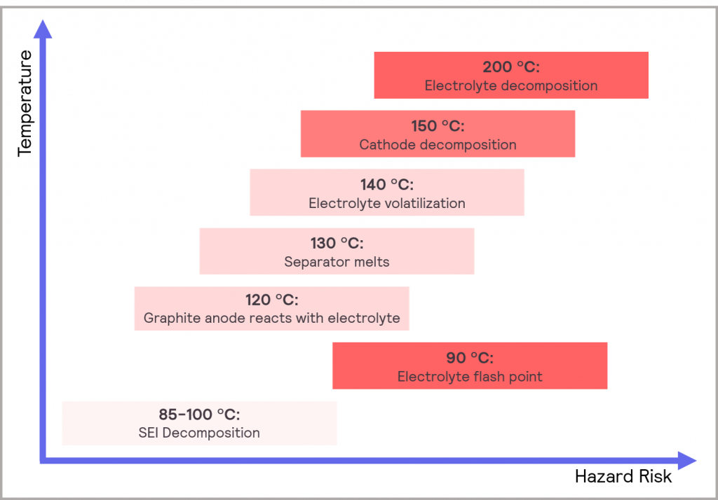
Figure 19: typical cascade of potential effects when a Li-ion cell overheats
Low Temperature
Although the focus is often on high temperatures and overheating, low temperatures can also induce a thermal runway, in extreme cases.
A number of challenges result from operating batteries at low/freezing temperatures [8]:
- Slower kinetics, leading to a slower rate charge transfer
- Lower electrolyte conductivity
- Increased SEI resistance
- Low solid-state lithium diffusivity in graphite
This will lead to charging difficulties, capacity fade, and power attenuation. It can also lead to lithium plating at the anode (graphite surface) during charging. These lithium deposits are no longer involved in subsequent electrode reactions, which is the main reason for the capacity fade. The deposits can also form dendrites, which can pierce the separator and induce an Internal Short Circuit (ISC) and subsequent thermal runaway.
Adiabatic calorimeters are ideally suited for performing thermal stress tests. They incrementally heat the cell or battery until self-heating is detected. They then maintain adiabatic conditions so that the cell or battery continues to self-heat, possibly until destruction. The technique allows the onset temperature of the thermal runaway to be detected and the rate of heat generation during cell failure to be determined accurately due to the well-defined and controlled test conditions. This information can be used to help define the safe working temperature of the battery. In addition, in-situ thermal mapping can be used to highlight regions of the battery which generate more heat when subjected to external thermal stresses [19]. Case Study 3 describes an investigation using the BTC-500 to determine the onset temperature of a Li-ion pouch cell.
Electrical Stress
Electrical stress tests, such as over-charging and over-discharging, can help facilitate the determination of the maximum or minimum safe voltage and maximum safe current of a cell or battery.
Over-Charging
Over-charging is usually defined as when a battery is forcibly charged beyond its cut-off voltage, and is reportedly one of the main causes of EV battery failure [8]. It causes over-delithiation of the cathode, which leads to the breakdown and collapse of the material’s structure. This then leads to side reactions between the cathode and the electrolyte – it is this that then causes the rapid increase in temperature in the cell. Often the reactions can be very violent, releasing a lot of gas and heat [20].
At the same time, over-charging will result in more rapid dissolution of the transition metal from the cathode into the electrolyte, which will then deposit on the anode surface. This plating will cause a significant increase in impedance, resulting in capacity fade of the anode [21] [22].
Similarly, the anode will not be able to accept the greater level of lithium ions now available due to the over-charge. This will result in metallic lithium depositing on the anode surface, which will then react with the electrolyte. This leads to a further impedance increase and heat generation [23]. The deposited lithium can also form dendrites, which can puncture the separator and cause an internal short circuit (ISC) and result in a thermal runaway situation, as depicted in Figure 16. Figure 20 illustrates the consequences of over-charging an 8 Ah Li-ion pouch battery based on NMC-graphite chemistry to 5V (instead of the safe maximum voltage of 4.5V).
Adiabatic calorimeters can be fully integrated with charge-discharge units to conduct overcharging electric stress tests. This not only enables the maximum safe voltage to be determined, but it also provides insight into the severity of the consequences when these safe operating limits are exceeded. This is because the instruments allow the test to be conducted under adiabatic conditions, simulating a worst-case scenario when no dissipation of the heat generated by the battery has taken place. This allows the consequences of malfunction to be realistically measured and as the test environment is well-defined, it allows comparison between different batteries.
In order to increase robustness to over-charging, research efforts within Cell Development are focused on improving the structural stability of the cathode and the thermal stability of the electrolyte at high voltage. For example, lithium iron phosphate (LFP) is much more thermally stable than the likes of NMC or LMO (however, it does have a lower energy density, again demonstrating the trade-off between battery attributes).
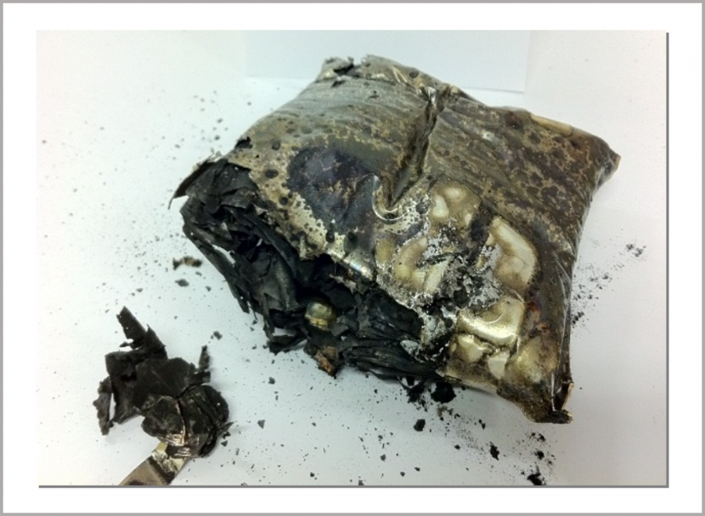
Figure 20: Li-ion NMC-graphite battery after over-charging to 5V in an adiabatic BTC
Over-Discharging
Exceeding the maximum safe current of a battery (i.e., over-discharging) could lead to the cell overheating and potentially a thermal runaway situation. Discharging a battery to a voltage below its lower limit will lead to the decomposition of the SEI. In doing so, it will lead to cell swelling as gases are generated. It will also indirectly lead to a reduction in capacity, as subsequent recharging steps will lead to the formation of new SEIs, which will consume active lithium ions and electrolyte. Similarly, an over-discharge will cause the copper current collector of the anode to be oxidized. It will subsequently dissolve in the electrolyte and the copper ions will migrate to the cathode before forming copper deposits on the cathode during battery charging. The deposits can form dendrites on the cathode, which can cause the separator to be penetrated, inducing an internal short circuit (ISC) and potentially a thermal runaway.
Therefore, it is vital to be able to determine what the maximum safe current of a battery, or C-rate, is so that a suitable overcurrent protection device can be implemented to limit the current. Defining what the C-rate is for a battery can be determined by exploring the impact of different discharge rates on a battery.
As discussed previously, adiabatic calorimeters can be integrated with a charge-discharge cycler, which allows the battery temperature during charging and discharging cycles to be measured. The system can be set up to automatically run repeated cycles, enabling information on the longer-term stability of the battery to be determined. It can be used to explore battery over-discharge behavior over a range of discharge rates [24]. The advantage of placing the battery inside an adiabatic calorimeter like the BTC-130 and the BTC-500 during the test is that the temperature changes will accurately indicate the energy changes taking place in a worst-case scenario where no heat dissipation is taking place. The test is similar to the over-charging test, except whereas in the over-charging test the current is at a normal and safe value and the battery is charged to higher voltages, in the over-discharge test, the voltage is kept within the safe maximum voltage, and the discharging current is pushed beyond the safe operating limits. Case Study 4 describes an investigation exploring the impact of high discharge rates on Li-ion batteries using the BTC-500.
External Short-Circuit
Thermal runaways can arise from both internal and external stimuli. An external short circuit will lead to self-heating and the resultant cell temperature increase can result in a thermal runaway. The BTC-130 and the BTC-500 can be equipped with the means to deliver an electrically induced external short circuit so that the impact and consequences can be evaluated. A visual record of the event can also be captured from integrated camera footage.
Mechanical Stress
This is normally divided into two types of stress: crush/collision and penetration [14]. The crush test simulates the deformation of the battery caused by, for example, a vehicle crash or by sitting down forcefully on a phone. As Figure 16 illustrates, the impact can cause an internal short circuit directly, or it can result in the generation of particles which will then induce an internal short circuit. Similarly, penetration tests, such as a nail/spike test, can cause a separator failure which then results in an internal short circuit. An internal short circuit will lead to increased self-heating and may result in a thermal runaway situation. The spike test can also cause the cell to be forced open, leading directly to material and gas ejection, possibly followed by cell fire. These tests can help provide an indication of the structural stability of the cell.
The BTC-130 and the BTC-500 can be equipped to perform a range of puncture tests within a safe environment for operators to carry out the test. Thermal data on the severity of the incident can be acquired and the integrated camera enables the unfolding event to be visually captured. Images depicting the moments immediately before and after a nail penetration test on a Li-ion pouch cell are illustrated in Figure 21.

Figure 21: immediately before and after a nail penetration test on a Li-ion pouch cell
Understanding Thermal Runaway and Thermal Propagation
Developing a deeper understanding of the mechanisms behind thermal runaway and thermal propagation can inform safety protocols in module and pack design, and also provide insight for future cell development.
In general, most extreme conditions result in thermal stress on the cell or battery, which can lead to a thermal runaway. The extent of the thermal runaway will depend on factors such as the capacity of the cell, the cell type, the cell history, the cathode/anode material, the electrode composition, and the state of charge (SOC) of the battery [14]. Therefore, the data obtained from the stress tests performed in the BTC-130 and BTC-500 can be used to model a cell’s predicted behavior [3]. Successive onset temperatures of decomposition of components within the cell can be detected, and the rate of heat generation during the failure determined. This data can be combined with data from structural analysis tools, such as X-ray CT imaging and scanning electron microscopy, to help decipher the series of events that a Li-ion battery undergoes during failure [5]. The external analysis of the composition of any evolved gases collected can provide insight into the chemical reactions that are taking place during the thermal decomposition, furthering mechanistic understanding of the thermal runaway.
The BTC-500 also enables the triggering of a thermal runaway in a cell at a specific position within the module via a mechanically- or electrically-induced short circuit. This can provide information on how a thermal runaway propagates within a module, and the magnitude of the thermal event can be characterized. This information can be used to develop models of module behavior and can also be used to inform mitigation measures within the module design to ensure heat dissipation is greater than heat generation.
CASE STUDY 3:
Detecting the Onset Temperature of a Thermal Runaway
The BTC-130 and BTC-500 can be used to carry out a so-called “heat-wait-search” test to determine the point at which cell self-heating starts and hence define the maximum safe working temperature. This involves heating the sample in small steps, and at the end of each step, the system “waits” to see if the battery is generating heat that can be measured by a temperature rise (the so-called “search” step). Figure 22 illustrates this test, in which, in this case, the sample did not thermally runaway at any temperature tested.
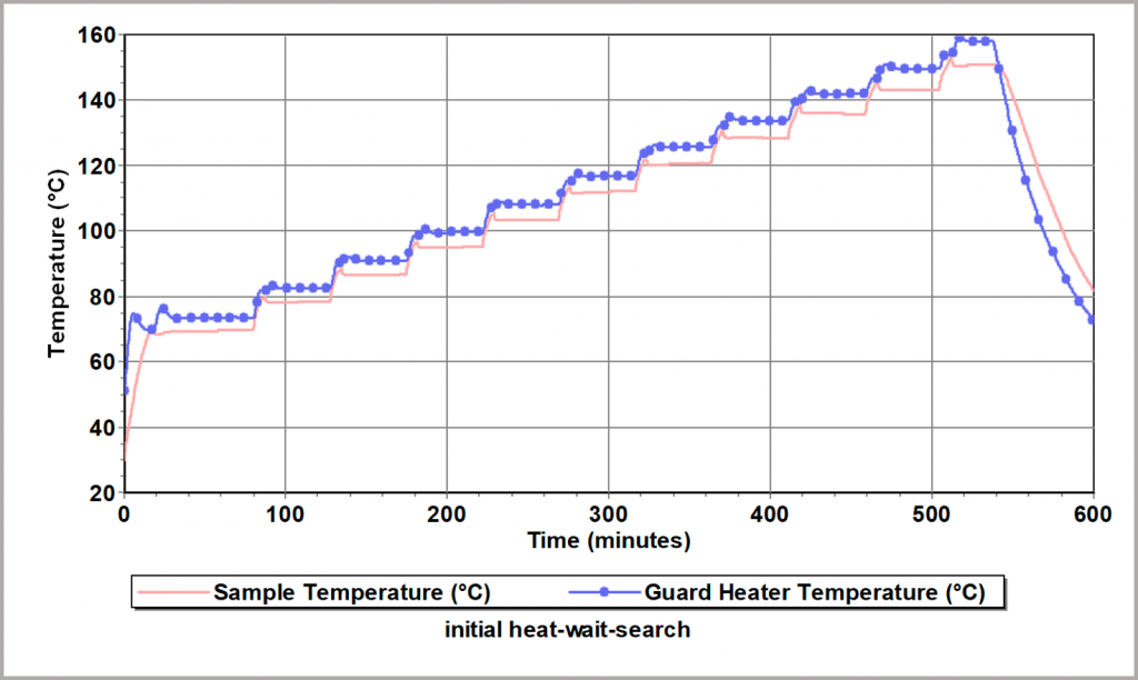
Figure 22: Heat-Wait-Search Test for evaluation of thermal stability
Figure 23 provides the test data for a pouch type Li-ion battery with a 5 Ah rating. The “search” procedure starts at 35 °C and as no heat generation from the cell has been detected, the battery is heated again. This stepwise heating is repeated until self-heating within the battery can be detected. In this example, it was found to be around 120 °C. This is essentially the maximum safe temperature of the cell. When this point is detected, the instrument maintains adiabatic conditions so that the battery continues to heat itself until the chemicals are consumed and the cell is destroyed. Figure 24 illustrates the state of the battery before and after the runaway has occurred.
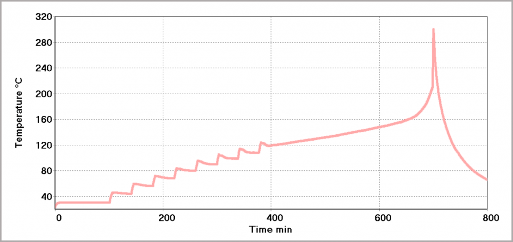
Figure 23: Heat-Wait-Search Test to determine thermal stability of a Li-ion pouch battery
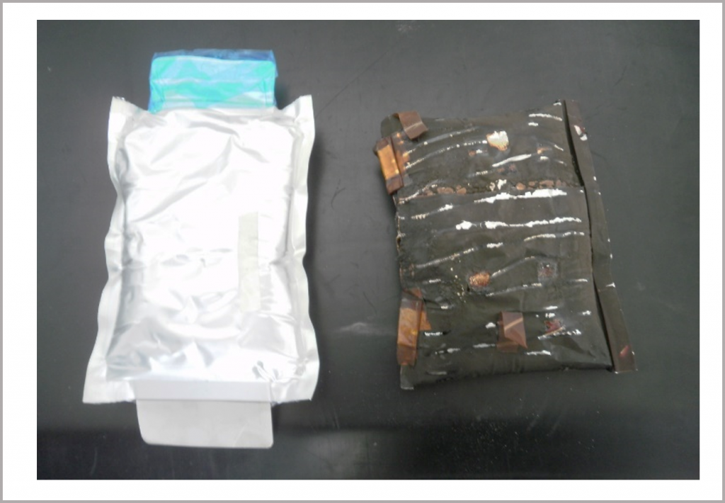
Figure 24: Li-ion pouch cell before (left) and after (right) it has been subject to a thermal runaway
CASE STUDY 4:
Exploring the Impact of Higher Discharge Rates on Li-ion Batteries
A 3-cell, 2.2 Ah Li-ion polymer battery was subjected to a series of charging-discharging cycles, as illustrated in Figure 25. During charging (at 2 A), the battery cools (endothermic reaction) and when discharging (at 3 A), heat is produced, leading to a rise in temperature. Overall, there is a rise in temperature after each cycle, as the discharge produces much more heating than the cooling effect of charging. As can be seen, eventually the temperature stabilizes at between 55 – 65 °C. In this example, the charging/discharging currents fall within the safe operating limits of the battery, and although the battery temperature rises, it does not lead to a problem and safe long-term cycling is demonstrated.
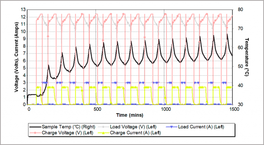
Figure 25: cyclic charging/discharge a battery pack inside an adiabatic calorimeter
The same battery was then subjected to higher charging and discharging currents, as illustrated in Figure 26. As before, the temperature rises during discharging (now 15 A) and falls during charging (now 5 A). However, this time there is now a continued rise in temperature and after only a few cycles, the battery goes into a thermal runaway. The data from the BTC-500 shows that this onset temperature is around 110 °C.
At this elevated temperature, the battery quickly develops an internal short and can no longer be charged. As a result, the cycler switches back and forth rapidly, reflected in the pink trace in Figure 26.
The integrated video camera in the BTC-500 is able to capture the thermal runaway unfolding, and some selected images are illustrated in Figure 27.
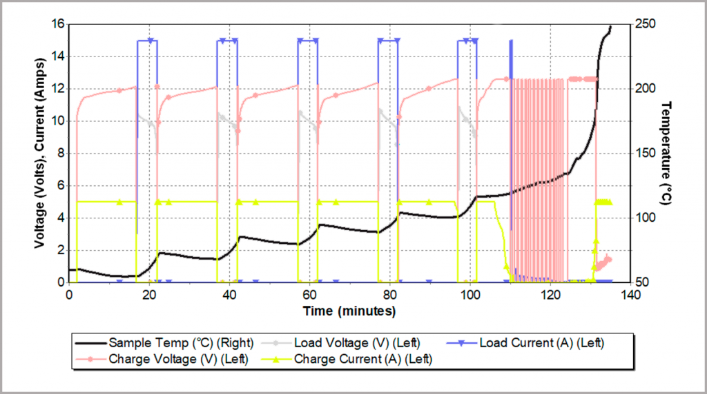
Figure 26: thermal runaway resulting from fast charging/discharging rates inside an adiabatic calorimeter
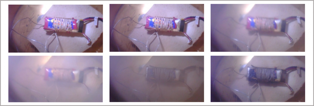
Figure 27: Li-ion polymer battery undergoing thermal decomposition; images from the integrated video camera in the BTC-500
Solutions in Battery Technology Testing
Understanding battery thermal behavior is critical in the development and manufacture of safe, efficient batteries. The need for more powerful batteries with higher energy densities generally results in the use of more hazardous materials and the potential for the development of more dangerous situations, which need to be thoroughly understood and managed. Furthermore, the thermal behavior of batteries is intrinsically linked to their electrical performance. Optimizing these attributes and widening the safe and optimum operating range of batteries necessarily requires a developed understanding of the relationship between the battery thermal behavior and electrical performance.
It is important to be able to probe battery behavior over different zones of operation throughout battery development in order to assess the battery response to these different conditions. These considerations are summarized in Figure 28. Within Cell Development, this knowledge and understanding can help facilitate the development of batteries with superior attributes in terms of safety, lifespan and performance. There is a need to understand the thermal hazard posed by cell components, so that appropriate precautions can be taken during cell development to mitigate the risk of thermal runaway occurring. The BTC-130 is well-equipped to perform the required hazard assessment on these materials, enabling the thermal stability of the compounds to be characterized. Beyond this, there is a broader aim within Cell Development to develop batteries with superior attributes, be that a longer lifespan, a better electrical performance over a broader range of temperatures or an improved thermal stability. For this, there is a need to characterize differences in cell behavior. The BTC-130 and the BTC-500 can provide information on the cell response in the Dangerous Zone of operation, enabling researchers to probe thermal stability characteristics and enhance understanding of the causes of battery failure. In contrast, the iso-BTC can probe the cell response in the Optimum and Safe Zones of operation, allowing developers to characterize the cell’s performance within normal operation.
For Cell Assembly, and specifically within Quality Control, it becomes important to characterize the bahavior of the cell. Probing battery behavior provides a means of confirming a stated performance, which can be utilized by cell manufacturers and cell integrators alike.
Finally, within Cell Integration, the information derived from investigating the battery response to thermal and electrical stimuli can be used to help develop methods for mitigating the risk of thermal runaway. The iso-BTC is able to characterize the thermal behavior of a cell, module or pack over normal use operating conditions, which can be used to inform thermal management requirements. The BTC-130 and the BTC-500 enable stress conditions to be applied to cells, modules and packs. The resultant battery responses to these stresses can be used to derive the safe operating limits of the battery. It is also possible to use the data from these tests to build up models and understanding of the mechanisms behind thermal runaways and thermal propagation, which can then inform future strategies for cell development.
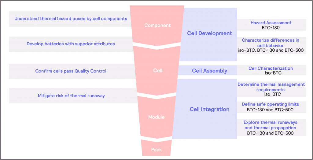
Figure 28: overview of considerations and solutions within the battery development workflow
References
| [1] | B. News, “Dreamliner: Boeing 787 planes grounded on safety fears,” BBC, 17 January 2013. [Online]. Available: https://www.bbc.co.uk/news/business-21054089. [Accessed 17 September 2020]. |
| [2] | F. O. o. S. a. H. M. Safety, “Events with smoke, fire, extreme heat or explosion involving lithium batteries,” 02 August 2020. [Online]. Available: https://www.faa.gov/hazmat/resources/lithium_batteries/media/Battery_incident_chart.pdf. [Accessed 17 September 2020]. |
| [3] | A. Abada, M. Petit, A. Lecocq, G. Marlair, V. Sauvant-Moynot and F. Huet, “Combined experimental and modelling approaches of the thermal runaway of fresh and aged lithium-ion batteries,” J. Power Sources, vol. 399, pp. 264-273, 2018. |
| [4] | G. Xu, L. Huang, C. Lu, X. Zhou and G. Cui, “Revealing the multilevel thermal stability safety of lithium batteries,” Energy Stor. Mater., vol. 31, pp. 72-86, 2020. |
| [5] | D. Patel, J. Robinson, S. Ball, D. Brett and P. Shearing, “Thermal Runaway of a Li-Ion Battery Studied by Combined ARC and Multi-Length Scale X-ray CT,” J. Electrochem. Soc., vol. 167, 2020. |
| [6] | SAE International, J2464:2009, “Battery Standards Safety Committee, Electric and Hybrid Electric Vehicle Rechargeable Energy Storage Systems (RESS) Safety and Abuse Testing, Surface Vehicle Recommended Practice,” Nov 2009. |
| [7] | Boston Consulting Group, “Batteries for Electric Cars: Challenges, Opportunities, and the Outlook to 2020,” BCG, 2016. |
| [8] | J. Duan, X. Tang, H. Dai, Y. Yang, W. Wy, X. Wei and Y. Huang, “Building Safe Lithium-Ion Batteries for Electric Vehicles: A Review,” Electrochemical Energy Reviews, pp. 3:1-42, 2020. |
| [9] | D. Lu, G. Xu, Z. Hu, Z. Cui, X. Wang, J. Li, L. Huang, X. Du, Y. Wang, J. Ma, X. Lu, H. Lin, C. Chen, A. Nugroho, L. Tieng and G. Cui, “Deciphering the Interface of a High-Voltage (5 V-Class) Li-ion Battery Containing Additive-Assisted Sulfolane-Based Electrolyte,” Small Methods, vol. 3, no. 1900546, 2019. |
| [10] | Y. Wang, Z. Zhang, L. Dong and Y. Jin, “Reduced shuttle effect by dual synergism of lithium-sulfur batteries with polydopamine-modified polyimide separators,” J. Membr. Sci., vol. 595, no. 117581, 2020. |
| [11] | H. Zappen, G. Fuchs, A. Gitis and D. Sauer, “In-Operando Impedance Spectroscopy and Ultrasonic Measurements during High-Temperature Abuse Experiments on Lithium-Ion Batteries,” Batteries, vol. 6, no. 25, 2020. |
| [12] | J. Robinson, D. Finegan, T. Heenan, K. Smith, E. Kendrick, D. Brett and P. Shearing, “Microstructural Analysis of the Effects of Thermal Runaway on Li-Ion and Na-Ion Battery Electrodes,” J. Electrochem. En. Conv. Stor., vol. 15, 2017. |
| [13] | J. Zhang, L. Su, Z. Li, Y. Sun and N. Wu, “The Evolution of Lithium-Ion Cell Thermal Safety with Aging Examined in a Battery Testing Calorimeter,” Batteries, vol. 2, no. 12, 2016. |
| [14] | V. Ruiz, A. Pfrang, A. Kriston, N. Omar, P. Van den Bossche and L. Boon-Brett, “A review of international abuse testing standards and regulations for lithium ion batteries in electric and hybrid electric vehicles,” Renewable and Sustainable Energy Reviews, pp. 1427-1452, 2018. |
| [15] | H. Popp, N. Zhang, M. Jahn, M. Arrinda, S. Ritz, M. Faber, D. Sauer, P. Azais and I. Cendoya, “Ante-mortem analysis, electrical, thermal, and aging testing of state-of-the-art cylindrical lithium-ion cells,” Elektrotech. Inftech., vol. 137, pp. 169-176, 2020. |
| [16] | G.-H. Kim, J. Gonder, J. Lustbader and A. Pesaran, “Thermal management of batteries in advanced vehicles using phase-change materials,” The World Electric Vehicle Journal, vol. 2, no. 2. |
| [17] | D. H. Doughty and C. C. Craft, “Electric Energy Storage System and Abuse Test Manual for Electric and Hybrod Vehicle Applications, SAND2005-3123,” Sandia National Laboratories, 2006. |
| [18] | H. Li, C. Liu, X. Kong, J. Cheng and J. Zhao, “Prediction of the heavy charging current effect on nickel-rich/silicon-graphite power batteries based on adiabatic rate calorimetry measurement,” J. Power Sources, vol. 438, no. 226971, 2019. |
| [19] | Z. Li, J. Zhang, B. Wu, J. Huang, Z. Nie, Y. Sun, F. An and N. Wu, “Examining temporal and spatial variations of internal temperature in large-format laminated battery with embedded thermocouples,” J. Power Sources, vol. 241, pp. 536-553, 2013. |
| [20] | Q. Yuan, F. Zhao, W. Wang, Y. Zhao, Z. Liang and D. Yan, “Overcharge failure investigation of lithium-ion batteries,” Electrochimica Acta, vol. 178, pp. 682-688, 2015. |
| [21] | X. Wu, Z. Wang, X. Li, H. Guo, Y. Zhang and W. Xiao, “Effect of lithium difluoro(oxalato)borate and heptamethyldisilazane with different concentrations on cycling performance of LiMn2O4,” Journal of Power Sources, vol. 204, pp. 133-138, 2012. |
| [22] | D. P. Abraham, T. Spila, M. M. Furczon and E. Sammann, “Evidence of Transition-Metal Accumulation on Aged Graphite Anodes by SIMS,” Electrochemical and Solid State Letters, vol. 11, no. 12, 2008. |
| [23] | M. Ouyang, D. Ren, L. Lu, J. Li, X. Feng, X. Han and G. Liu, “Overcharge-induced capacity fading analysis for large format lithium-ion batteries with LiyNi1/3Co1/3Mn1/3O2 + LiyMn2O4 composite cathode,” Journal of Power Sources, vol. 279, pp. 626-635, 2015. |
| [24] | D. Wang, L. Zheng, X. Li, G. Du, Z. Zhang, Y. Feng, L. Jia and Z. Dai, “Effects of Overdischarge Rate on Thermal Runaway of NCM811 Li-Ion Batteries,” Energies, vol. 13, no. 3885, 2020. |