Investigating a Sponge Metal Catalysts in a Trickle Bed Reactor for Continuous Hydrogenation Inflow
Antonella Carangio, 1 Lee J. Edwards, 1 Eneritz Fernandez-Puertas, 1 Jerome F. Hayes,1 Maciej Kucharski, 1 Graham W. Rutherford, 2 Katherine M. P. Wheelhouse, 1 Glynn D. Williams 1
1 Chemical Development, GlaxoSmithKline, Gunnels Wood Road, Stevenage, United Kingdom
2 Clinical Supply Chain – Pilot Plant Operations, GlaxoSmithKline, Park Road, Ware, United Kingdom
In this study, the H.E.L. FlowCAT was used to optimize inflow the reductive hydrogenation of an aliphatic nitro intermediate using a sponge nickel catalyst in a trickle bed reactor. Once optimal conditions were established, 1.2 kg of reagent was successfully reduced via the FlowCAT, with a yield of approximately 90% over a period of 19 hours. This work was carried out by the Chemical Development team and the Clinical Supply Chain team at GSK, to whom all work is accredited. The full publication can be found on ACS here (1).

Introduction
Continuous flow processing – or simply flow chemistry – encompasses chemical processes where reactions occur in a continuous stream. This represents a fundamental departure from traditional chemistry techniques, where reactions are carried out in distinct batches. Flow chemistry has attracted a great deal of attention over the last 20 years, with proponents citing numerous advantages, including more efficient mixing in multiphasic systems, greatly enhanced temperature control, and alignment with “Green Chemistry” principles relating to efficiency and safety. (2) (3) (4)
In the manufacture of active pharmaceutical ingredients (APIs), the decision of whether to conduct a specific reaction in batch, or in flow is often debatable, with both modalities offering distinct advantages and disadvantages. However, in many ways, the reduction of an aliphatic nitro compound via sponge metal catalyst (as presented here) is a useful example for in-flow processing. Some of the reasons for this are:
- Such reactions are highly exothermic and susceptible to thermal runaway (5). Carrying out the reaction in flow enables greatly enhanced temperature control compared with batch processing, improving safety and reproducibility and enabling higher temperature and pressure operating windows. This is due to the reduced amount of reagent under reaction conditions at any one time.
- The process is a triphasic reaction of a gas, solid and liquid. In flow processing can provide more efficient mixing and mass transport compared with batch processing.
- Sponge metal catalysts, such as Raney nickel, are typically designed out of API reaction processes when they are scaled up due to handling difficulties. Placing these catalysts in packed-bed reactors and running the process in flow reduces potential exposure to these substances, avoids a hazardous filtration step, and makes it easier to recycle spent catalysts. (6)
Following a preliminary comparison of 9 catalysts, 3111A Raney nickel was selected for further investigation. A H.E.L FlowCAT was chosen as the platform to investigate further scale-up of a trickle bed system using 3111A Raney nickel for the reductive hydrogenation of (S)-7-methyl-7-(nitromethyl)-1,4-dioxaspiro[4.5]decane – Compound 1 (Figure 1).
The FlowCAT enabled researchers to precisely control gas and liquid flow rate, reactant inlet pressure and temperature, and reactor temperature to determine the optimal conditions for the reduction process within a trickle bed reactor.

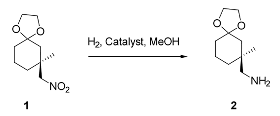
Figure 1: Hydrogenation of (S)-7-methyl-7-(nitromethyl)-1, 4-dioxaspiro[4,5]decane
Materials and Method
In order to ensure reproducible results on scale-up, the pressure drop and flow regime of the system were kept constant. This was made possible by the FlowCAT’s easily interchangeable reactors, enabling the bed depth of the catalyst to be kept constant while increasing the diameter of the column, (Figure 2).
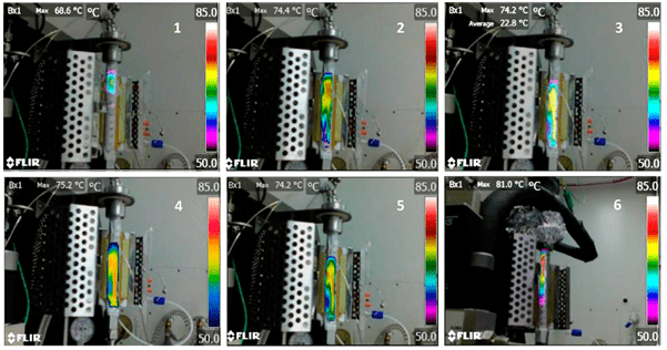
A FLIR E5 thermal imaging camera was also utilized to determine the outside wall temperature of the reactor. This enabled the thermal front of the reaction to be followed, allowing monitoring of the reaction exotherm and catalyst stability.
Reaction conditions were varied systematically in order to optimize the yield of the hydrogenated compound 2 (Figure 1).

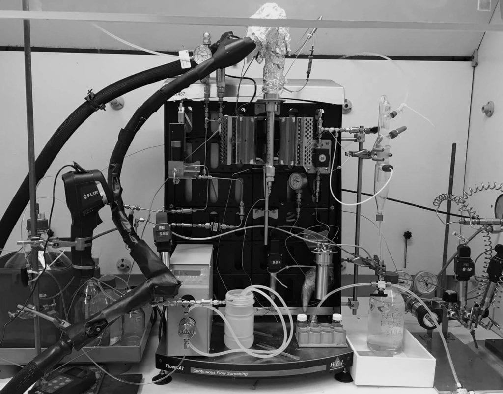 Figure 2 – FlowCAT experimental set-up
Results and Discussion
Detailed measurements of the thermal profile of the reactor bed enabled optimization of the process parameters by varying flow rate and inlet temperature.
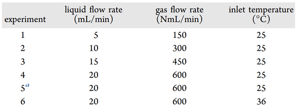 Table 1 – List of Experiments Performed To Examine the Effect of the Liquid and Gas Flow Rates on the Location of the Hottest Point within the Column
Further optimization of the reaction was achieved by monitoring yield while varying flow rate, inlet temperature, pressure, and concentrations.
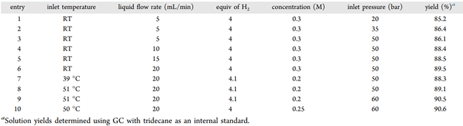 Table 2 – List of Experiments Performed in Flow – Operating Parameters, and the Product Yields Obtained
By fine-tuning the inlet temperature of the liquid feed line, the researchers could control the position of the hottest part of the column to better use the catalyst — the resulting process delivered reactant conversion near 100% and a yield of 90.6%. To demonstrate the scalability of the process, an extended reduction of Compound A was run over a period of 19 hours.
The FlowCAT was fitted with a 12 mm internal diameter reactor containing 43 g of 3111A Raney nickel. The system was then pressurized to 100 bar with MeOH (20 mL/min) and nitrogen (1000 NmL/min) for 20 minutes to settle the catalyst. After which, the system was depressurized, and a layer of quartz and a PTFE frit were inserted into the top of the column. 1.12 kg of the reactant was dissolved in MeOH (21.5 L, 19 vol) and fed into the reactor at 20 mL/min with H2 (4.5 equiv, 561 NmL/min, 60 bar).
The efficiency and selectivity of the reaction was monitored via gas chromatography, with samples taken every 20 minutes. This showed no change in the product yield throughout the run (Graph 1).

 |
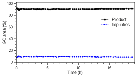 |
Left: Image 1 – Thermal images of the reactor for the experiments listed in Table 1. Right: Graph 1 – %GC Area of product and impurities of extended duration run
Conclusion
This study demonstrates the effectiveness of the FlowCAT system as a flexible tool for the determination of optimal parameters for in-flow processes. The FlowCAT was also used to prove scalability, successfully carrying out the reduction of a large amount of compound 1 over several hours, showing virtually no deactivation of the catalyst.
The H.E.L FlowCAT is a benchtop flow reactor optimized for high-pressure catalytic reactions. The unit provides a versatile and compact platform for catalyst process development, making it easy to trial multiple catalysts and optimize process parameters. Results from a FlowCAT can be directly applied to a full-scale flow reactor.
References and Further Reading
1. Evaluation of Sponge Metal Catalysts in a Trickle Bed Reactor for the Continuous Hydrogenation of an Aliphatic Nitro Intermediate. Antonella Carangio, Lee J. Edwards, Eneritz Fernandez-Puertas, Jerome F. Hayes, Maciej M. Kucharski, Graham W. Rutherford, Katherine M. P. Wheelhouse, and Glynn D. Williams. 10, s.l. : Organic Process Research & Development, 2020, Vol. 24.
2. The Hitchhiker’s Guide to Flow Chemistry. Plutschack, M.B, Pieber, B., Gilmore, K & Seeberger, P.H. 117, s.l. : Chem. Rev, 2017. 11796-11893.
3. Continuous Manufacturing – The Green Chemistry Promise? Rogers, L. &F. Jensen, K. 21, s.l. : Green Chemistry, 2019. 3481-3498.
4. Green Chemistry: Principles and Practice. Anastas, P. & Eghbali, N. rev, 39, s.l. : Chem. Soc, 2010.
5. Runaway Reaction Hazards in Processing Organic Nitro Compounds. Gustin, Jean-Louis. 1, s.l. : Org. Proc. Res. Dev., 1998, Vol. 2.
6. Managing Hazardous Reactions and Compounds in Process Chemistry. Ager, D.J. s.l. : American Chemical Society, 2014, Vol. 1181.