Characterization of the cooling performance for the multi-reactor PolyBLOCK 8
Aliko Chanda, Joseph Willmot
H.E.L Group, 9-10 Capital Business Park, Manor Way, London, WD6 1GW
This study investigated the temperature cooling capabilities of the PolyBLOCK parallel reaction block with different cooling modes. Three different solvents were investigated in four different reactors. The solvents used varied in boiling point, heat capacity, and viscosity. The cooling characteristics were evaluated with and without a chilling Silicone oil circulator connected to the PolyBLOCK. It was found that although solvents and reactor material can impact cooling rates, the PolyBLOCK 8 can provide consistent cooling.
Table of Contents
Introduction
The PolyBLOCK 8 is a parallel reactor block with in-built heating, cooling, and stirring capabilities. It can operate as a stand-alone reactor system, and it is also found in many other products such as the ChemSCAN or BioXplorer range. The PolyBLOCK 8 has eight independently controlled reaction zones in a compact footprint. Depending on the intended use, the reactor vessel will typically be glass or metal. Glass is often used for general synthesis and laboratory work, metal – typically SS316 or HC276 – for high-pressure applications.
This study demonstrates the cooling capabilities of the PolyBLOCK 8 by testing temperature control methods with various solvents, and reactors. Thereby providing a valuable guide to selecting the right combination of these factors when designing an experiment.
Materials and Method
The PolyBLOCK 8 in this study was used in standard laboratory conditions, controlled via labCONSOL® software. In all experiments, glass reactors with PTFE lids of 50 mL, 100 mL, or 150 mL volume were placed in mantles 1 to 4 while positions 5 to 8 had SS316, 200 bar rated metal reactors of either 16 mL or 50 mL volume. – Detailed in Table 1.
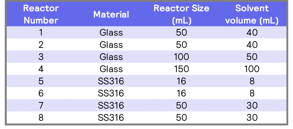
Table 1. Details of all reactors, including size material of reactor and solvent volume.
Deionized water (with a conductivity below 5 µS), Methanol (CAS no.: 67-56-1), and Silicone oil (Huber P20-275- 50) were the solvents used for these tests. Six-blade PTFE Rushton impellers were used in the glass reactors, and SS316 anchor impellers were used in the metal reactors. In all cases, stirring was provided via magnetically coupled agitation provided by the PolyBLOCK in-built magnetic stirrer at 400 rpm. In addition, a Huber Unistat 430 was attached to the PolyBLOCK to provide active cooling.

Results and Discussion
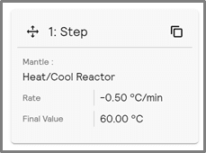
The labCONSOL® software can operate the PolyBLOCK in various modes, such as Heat/Cool Reactor (ramping reactor temperature) or Constant Reactor Temperature.
Heat/Cool Reactor changes the reactor temperature at a defined rate -see figure 1 for example.
In contrast, Constant Reactor Temperature Control (figure 2) cools the reactor contents to a specified temperature as quickly as possible. Both cooling modes were investigated.
Along with the heating characterization, cooling characterizations were determined on the PolyBLOCK. For ease of interpretation, example data from the following reactors will be shown: R1 (glass), R4 (glass), R5 (SS316), and R8 (SS316).
 |
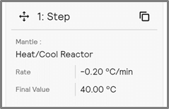 |
| Figure 1. Heat/Cool Reactor plan cooling by -0.5 °C/min to 60 °C | Figure 2. Step of Constant Reactor cooling to 40 °C |
The reactors were cooled at a rate of -0.5 °C/min to 60 °C (graph 1) and then -0.2 °C/min to 40 °C.
Cooling at -0.5 °C/min required approximately 45 minutes to cool the reactor contents by 20 °C (from 60 °C to 40 °C). Cooling at -0.2 °/min required approximately 108 minutes to cool the reactor contents by 20 °C (from 40 °C to 20 °C).
Slow cooling rates are likely to occur when there is no active cooling present on the system.
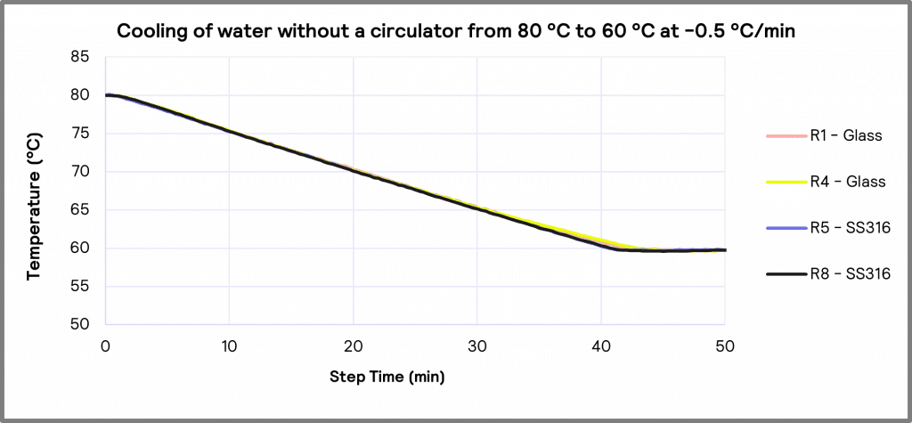
Graph 1. Cooling of water on Heat/Cool Reactor temperature control mode without a circulator from 80 °C to 60 °C at -0.5 °C/min
The tests with Methanol were conducted with the circulator attached, significantly increasing the system’s cooling capacity. In these experiments, cooling rates between –2 °C/min and -10 °C/min were evaluated.
All reactors achieve a maximum cooling rate of -2 °C/min for Methanol, demonstrating that slower cooling profiles will provide the best temperature control (graph 2).
This study also characterized cooling rates of Silicone oil between 120 °C and 40 °C. Much like the Methanol characterizations, cooling by –10 °C/min was not possible. The best glass and high-pressure results were those when reactor temperature cooling was at -4 °C/min.
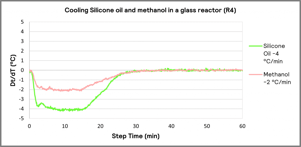
Graph 2. Dt/dT profile of Methanol (circulator temperature 10 °C) and Silicone oil (circulator temperature 30 °C) on Heat/Cool Reactor temperature control mode
When cooling Silicone oil in Constant Reactor Temperature control mode from 120 °C to 40 °C, all reactors achieved a maximum cooling rate of -9.0 °C/min with the oil temperature at 30 °C. This is due to the cooling capacity available from the circulator (graph 3). This was repeated with Methanol between 50 °C down to 10 °C. Though cooling was achieved at this lower temperature, the cooling rate was less stable at -4 °C/min or above.
When cooling in Constant Reactor Temperature mode, the reactor zones achieved a lower temperature in a shorter time with active cooling. With active cooling, circulator oil is continuously flowing through the PolyBLOCK’s oil cell. The reactor’s material and volume of solvent effect constant cooling rates, as shown in the graph below.
In Graph 4, it is observed that Reactors 4 and 5, a glass and a high-pressure reactor, take the same time to cool, possibly due to their similar vessel sizes. All reactors required approximately 30 minutes to cool 80 °C at varying rates. Graph 5 shows the benefits of cooling at -2 °C/min with active cooling, where all reactors behave uniformly.
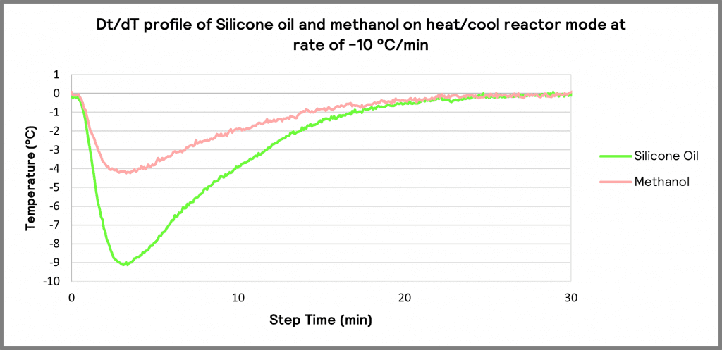
Graph 3. Dt/dT profile of Silicone oil (circulator temperature 30 °C) and Methanol (circulator temperature 10 °C) on Heat/Cool Reactor mode at a rate of -10 °C/min
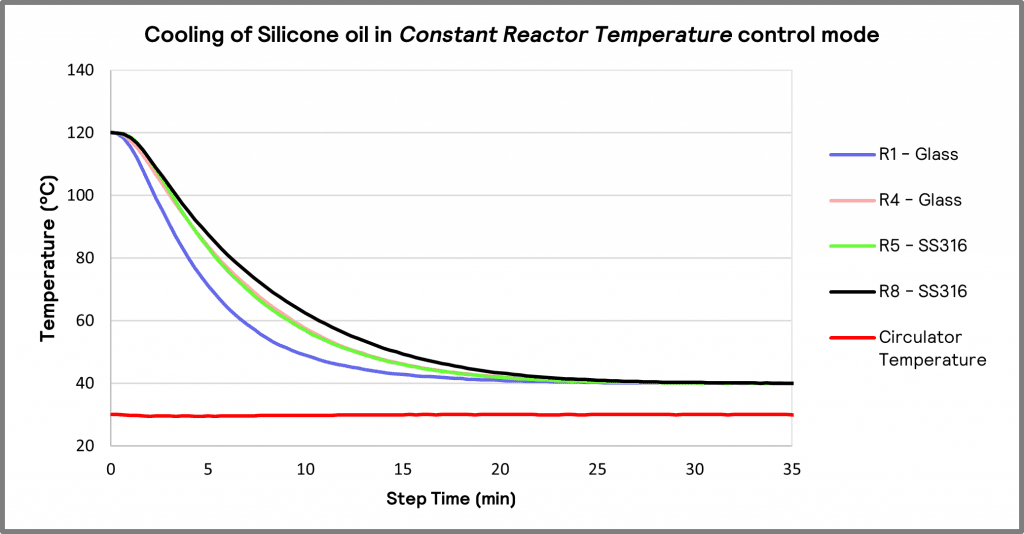
Graph 4. Cooling of different volumes of Silicone oil (circulator temperature 30 °C) in Constant Reactor Temperature mode
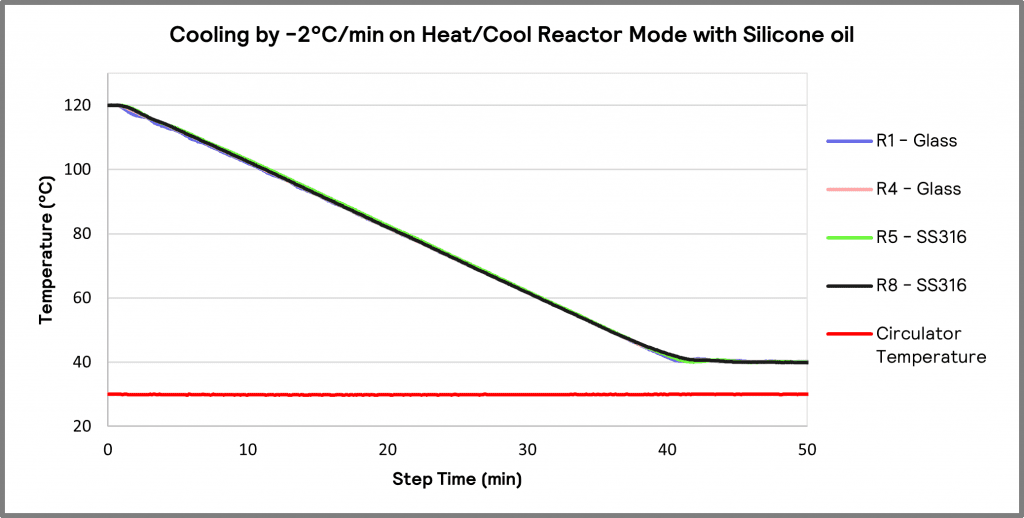
Graph 5. Silicone oil (circulator temperature 30 °C) cooling 80 °C by -2 °C/min on constant reactor mode

Conclusion
Providing active cooling is massively beneficial when using the PolyBLOCK 8, especially when rapid cooling rates are required. Cooling at slower rates than -6 °C/min will give consistent results in all reactors.
This data also highlights the importance of other factors such as solvents, solvent volume, and reactor material that may cause varying cooling profiles. However, using the Constant Reactor Temperature control mode will provide the maximum achievable cooling rates with a potential impact on temperature stability.
Acknowledgments
We want to thank the contribution of Dr. Paddy Delaney, for lending us a Huber Unistat 430 for these characterizations and other applications.