We are often asked what testing and data are needed to carry out vent sizing calculations. While each situation requires unique consideration, I thought it would be helpful to outline my typical approach. I’ll also shortly publish a companion article detailing why low-phi-factor adiabatic calorimetry is an ideal technique to generate the data needed for these tests.
What data is needed for vent sizing?
During the venting of a runaway reaction, the release rate must be sufficient to match the pressure rise rate at least (otherwise, obviously, the pressure in the reactor will continue to increase).
The essential information points used in the vent size calculations are:
1. Specific data on the reaction
- The pressure,
- The temperature,
- The rate of temperature rise, and,
- The rate of pressure rise.
2. The type of venting system
- Gassy
- Tempered, or
- Hybrid
3. The flow regime of the system
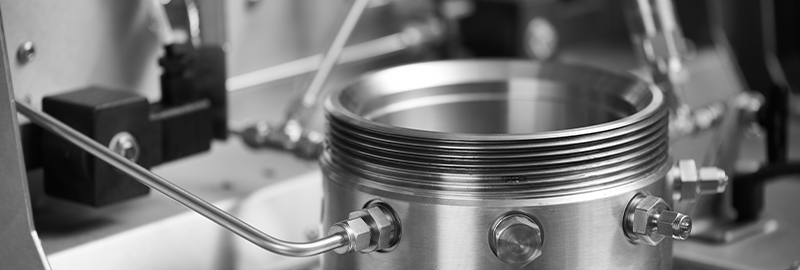
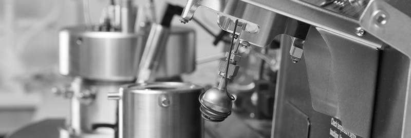
Given the potential for a violent runaway reaction, we want to obtain these data on a small (laboratory) scale rather than full-plant data. It is vitally important that any test data generated on a small scale will be relevant to the production-scale reactor’s conditions. A low Phi-factor adiabatic calorimeter is ideal for vent sizing and other applications for providing this relevant data.

Gassy, tempered or hybrid?
Where venting is used as a basis of safety [Ref 1, 2], it is important to realize that the mechanism that causes a pressure increase can be due to two factors:
-
- the generation of non-condensable gas – “Gassy” systems,
- increasing vapor pressure as the temperature increases – “Vapor pressure” or “tempered” systems.
Note that we often also talk about a third mechanism, a “hybrid” system, which is simply a combination of both – the pressure is due to both gas generation and vapor pressure.
With a vapor pressure system, during venting, the liquid will evaporate to maintain the vapor pressure equilibrium within the reactor, and the latent heat of evaporation in turn, will give a cooling effect that can temper the runaway.
Using a tempered system:
- The relief vent is sized so that the pressure is maintained at a constant level,
- The temperature is, in turn, primarily held constant by the vapor-liquid equilibrium
If the temperature is constant, the reaction rate is essentially also held constant. Therefore, the reaction will not continue to runaway to higher and higher rates, with an adequately sized vent. (I will add the caveat that runaway can restart should the solvent or most volatile component completely boil off)
Additionally, if the relief pressure is below the maximum working pressure (MAWP) of the reactor, some venting will occur before the pressure reaches the MAWP, and so a smaller vent size will likely be sufficient.
With a gassy system, there is no analogous cooling effect as the system vents. Therefore, in a gassy system, the vent should be designed for the maximum pressure increase rate expected from the reaction.
In hybrid systems, the pressure increase is due to both non-condensable gas generation and significant vapor pressure from the liquid. Hybrid systems can be further separated into tempered and non-tempered hybrids. They can then be treated as either a vapor pressure or a gassy system for vent sizing.
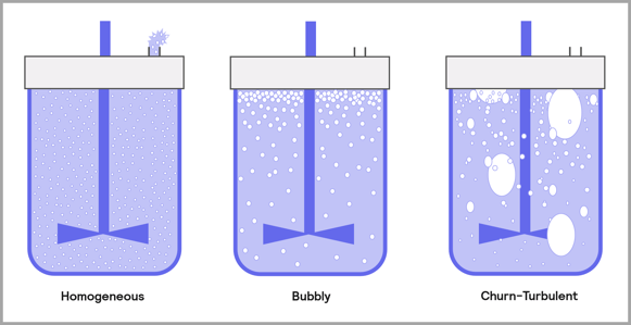
Flow regime
A further piece of information required for vent sizing is the flow regime. The flow from the vent may be single-phase gas or vapor, or more likely in the case of larger reactors, it will be two-phase of both liquid and gas/vapor. The two-phase flow regime can be foamy or churn turbulent, each with its own set of considerations.
Vent sizing data experiments
Typically, we use up to three tests to generate the data required, but often not all are needed. For example, it is common to assume a gassy system will be foamy. Should such assumptions result in a sensible and manageable vent size, then I would often stop there – further investigation might not be worth the effort. I would generally only investigate this further if the resulting vent was overly large or larger than an existing vent line on the reactor. A two-phase foamy system will invariably lead to a larger vent diameter than a churn turbulent regime, and a gassy system will give a more rapid runaway than a system with any tempering – either vapor pressure or hybrid.
Test 1 – Runaway data
The first test establishes the extremes of the runaway and the peak rates of temperature and pressure increases. This test is straightforward, and it is run in a low Phi-factor calorimeter. It is crucial to select the exotherm’s starting temperature to match what happens at a large scale. This may be higher than the “detected” onset shown in a heat-wait-search type test, as the rate of reaction will increase at higher temperatures. The temperature chosen will depend on whether the runaway reaction is a secondary decomposition or part of the desired reaction.
Suppose the reaction generates a very large amount of non-condensable gas, which will increase the pressure beyond the system’s limits. In that case, it is possible to open the test cell headspace to a separate pressure vessel, thereby effectively increasing the headspace volume or the volume occupied by the gas phase. The reaction will proceed unhindered, the amount of gas generated, and the rate of generation will remain the same, but the pressure increase (both rate and actual pressure) will be reduced due to the larger volume. The volume of the measured pressure and rate must be considered when looking at the vent size calculations. Of course, with the reduced gas pressure, this may lead to a situation where vapor pressure may become significant and give a cooling effect, or even lead to boil-over of the liquid. To mitigate these effects, we can pressurize the pressure vessel and the test cell to well beyond the liquid’s boiling point.
Test 2 – Tempering test
We use this test if a system is suspected to temper. In this, an open cell is used, and the reaction is allowed to run away until it reaches the set relief pressure point. If the reaction tempers, then material will be vented from the test cell. The temperature will then stabilize due to the cooling effect of venting. Once tempering is established and the data obtained, the pressure can be increased to the MAWP of the reactor, and if tempering occurs again, then we will have the data we need for the tempered vent sizing equations. If there is no tempering observed, we can assume that the system is non-tempering and use the gassy vent sizing equations using data from the runaway test.
One way to do this is with an open test cell in a Phi-TEC II, where we pressurize the containment vessel (and hence the cell) to the set pressure. The downside to this is that if anything is vented from the cell (and it is almost certain), resulting in (at best) a messy cleanup and replacement of the insulation, but chemical or corrosion damage is also possible.
I find that a better alternative is to connect the feed line of the test cell to an external pressure vessel, much like the runaway tests. The external vessel is manually pressurized to the relief set pressure (and then later to the MAWP). In this way, any material leaving the test cell will pass to an empty vessel that is much easier to clean afterward, even though the set-up is slightly more complicated.
Test 3 – Flow Regime test
The principle of this test is simple, the reaction is allowed to run away, then at a specified pressure, a valve is opened, and the test cell is vented. I usually vent to an open vessel, but the vessel can be closed if it is large enough. After correcting for differences in the headspace volume, the venting pressure is carefully chosen to suit the maximum pressure generation within the reactor. After venting, the valve is closed, and the system is allowed to cool. Once cool, the test cell is removed and weighed to measure how much of the initial sample remains.
- A foamy system will typically result in almost all the material being vented. Usually, less than 20% of the initial sample remains.
- A churn turbulent regime typically results in 40-60% remaining,
- A single-phase, gassy regime, usually leaves almost 100% of the sample remaining.
During this test, the containment vessel’s venting rate may not keep up with the test cell venting. In this case, it may be necessary to manually open a valve on the containment vessel to prevent crushing of the test cell (As the containment vessel would be at a higher pressure than that of the low Phi-factor test cell)
I am not a fan of the flow regime test. However, it is the best we can do on this scale, and it does give consistent results and a good indication of the likely flow regime. The limitations include:
- the actual gas generation and bubble rise velocity are not directly scalable
- the venting rate may not be the same as will be seen at the full-scale.
I will only run this test if I don’t want to assume two-phase foamy/homogeneous flow.
Although it is possible to estimate the flow regime theoretically, it is unlikely to be highly accurate. It requires knowledge of parameters such as surface tension of the liquid and viscosity of the gas. Since these factors are continually changing during thermal decomposition, and indeed we are unlikely to know the exact composition at any point, modeling becomes highly problematic.
Final notes
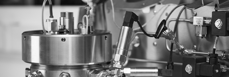
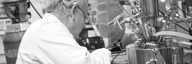
I use the Phi-TEC II to obtain all the data needed for vent sizing calculations. The actual relief line sizing requires a good understanding of the particular methods and equations. Pressure losses on downstream piping and equipment must also be taken into account and can significantly affect the size of the vent needed.
Generally, venting from full-scale reactors will be two-phase – invariably, this leads to much larger venting than single-phase vents.
Although venting is an acceptable basis of safety, it can lead to other problems, such as the disposal of effluent. It is often a better practice to deploy other mitigation procedures and use venting as rarely as possible.
References
- “Emergency relief system design using DIERS technology”, the Design Institute for Emergency Relief Systems (DIERS) project manual, AIChE 1992, ISBN 0 8169 0568 1
- Janet Etchells and Jill Wilday “Workbook for chemical reactor relief system sizing” HSE books, Contract research report 136/1998, ISBN 0 7176 1389 5.